
10Gb Ethernet vs sFPDP
Abstract: Front Panel Data Port (FPDP) has been the preferred interface for high speed data streaming in embedded applications since the VME era in the 1980’s. With the introduction of Serial FPDP in 2003, the supported cable lengths were significantly increased, and cabling greatly simplified. The update of VITA 17.1 to support 10Gbps, and recent ratification of VITA 17.3 further enhancing bandwidths, making sFPDP a very capable interface. Yet, with 10Gb Ethernet readily available in modern embedded systems, sFPDP is facing hard competition as the interface of choice for radar and other demanding data streaming applications.
This White Paper outlines the benefits and challenges of Ethernet compared to Serial FPDP for high performance data streaming applications in modern military systems.
1.
Introduction
1.1 Ethernet data streaming compared to sFPDP
Due to the very high performance and the low overhead, FPDP and the more recent serial FPDP (sFPDP) has been the preferred interface for high speed data streaming in embedded applications for many years.
With 10Gb (and beyond) Ethernet readily available in modern embedded systems, sFPDP is facing hard competition as the interface of choice for radar and other demanding data streaming applications.
Historically, sFPDP has been used primarily for point-to-point (or single transmitter, multidrop) data streaming. Ethernet has been the jack-of-all-trades – capable of any and all data transfer including data streaming. Supported by extremely flexible switching networks, tight processor integration and reliable connectivity, Ethernet has huge advantages over competing technologies. In many cases, those advantages will be sufficient to counteract the low latency and low overheads of sFPDP.
This Whitepaper considers the benefits and challenges of both options for demanding data transfer applications in modern military systems. sFPDP and Ethernet both have advantages and disadvantages, so the answer to the question depends on the application and on many system design parameters.
Before comparisons are possible, it is necessary to consider the different protocols which could be used with Ethernet – comparing sFPDP with UDP or TCP/IP is much more meaningful than comparisons with Ethernet as a whole.
Other factors in the comparison are what devices are available at each end of the data streaming link – i.e. which device is handling the data transfer. In many cases the source of data is an FPGA rather than a processor, but the receiving end is often a processor if Ethernet is considered. Some protocols are best suited to FPGAs and some are better for processors.
1.1.1 Baud rate vs data rate for serial links
Note that all serial links require clock recovery and DC balancing. Therefore, they must encode the data in such a way to ensure transitions occur even if all the data is 0. This is described in the format e.g. 8b/10b means 8bits of data is encoded as 10bits transmitted on the serial link. Encoding has an impact on the bandwidth. Through this document, the underlying link rate is referenced as the Baud rate, whereas the data rate is the bit rate.
e.g. serial 10GBASE-SR has a data rate as of 10Gbits per second, with a serial link operating at a baud rate of 10.3125Gbaud (64b/66b encoding).
2.
Ethernet
2.1 History
Since the commercial introduction of Ethernet in 1980 and standardization as IEEE 802.3 in 1983, Ethernet has gained widespread use in both military and civilian applications. Today, it is hard to imagine any device without built in network capability, that being anything from a wristwatch or a thermometer to a supercomputer.
As available bandwidth in Ethernet has steadily increased, the usefulness as a primary data transport interface has increased accordingly. With 10Gbit and beyond currently being readily available also in military embedded systems, it has sufficient bandwidth to compete with traditional interfaces such as FPDP. 10Gb Ethernet, 25Gb Ethernet, 40Gb Ethernet and 100Gb Ethernet are all in active use in the commercial world. Adoption into rugged systems is slower due to the need for wide operating temperature ranges.
There are many benefits with using Ethernet for data transport. Some of these are outlined in more detail in the following sections.
2.2 Physical Media
Ethernet is defined in the IEEE 802.3 set of standards.
2.2.1 Copper connections
Copper connectivity for Ethernet is typically the same across multiple different link speeds. RJ45 connectors can be used for 10Mb, 100Mb, 1Gb, 10Gb, 25Gb and even 40Gb Ethernet. Signal integrity concerns require that the cabling must improve to achieve reasonable connection lengths, but the connectivity and pinout remains the same. Auto-negotiation is a requirement in the standard.
Even at the lower frequency options, cable lengths are limited. Even with the best cables available, resistive losses and interference reduce the signal to noise ratio.
2.2.2 Optical connections
For longer cable lengths, lower weight, and higher degree of isolation from interference, optical cabling is used. A variety of modules are available to support this from tiny packages for embedded applications, to SFP+ (Small Form-factor Pluggable) with flexibility to change transceivers without modifying boards. The ubiquitous LC connector is often used for the individual fiber cable connections, with varieties also available with additional physical security for use in vibration or shock conditions. At the enclosure level, optical connectors are also available with the same protections from ingress which is provided by typical military 38999 connectors.
2.3 Common infrastructure and switching
One obvious advantage of Ethernet is the availability of Ethernet controllers. Most modern Single Board Computers (SBCs) and embedded computer systems have at least one Gigabit Ethernet controller built in. Some have several GbE interfaces, and increasingly 10Gb is part of the standard build. Further, Network Interface Cards (NICs) are available in many form factors. Consequently, utilizing Ethernet as the primary data interface might not need any additional hardware beyond what is already available in the system, or can be added to the system at a relatively low cost.
Note that for comparable performance to 10Gb sFPDP, a dedicated 10Gb Ethernet interface must be available and not used for any control functions or other data. For the reminder of this document, it is assumed that the 10GbE interface is dedicated to payload data and not used for anything else.
Although a single point to point connection will be sufficient, and even preferred, for many applications, a major advantage of Ethernet is the support for switched networks. Ethernet switches add a lot of flexibility to Ethernet compared to sFPDP and allows routing the payload data over a general purpose Ethernet network. Although simplifying or possibly eliminating the need for additional cabling, the switches also add undesired features to the system.
Any switch has a certain delay element associated with routing the data through the switch matrix. This delay adds latency to the data stream, affecting the total travel time for the data from the sensor to the processing unit. The switching delay can be further affected by other traffic in the system, causing not only a deterministic delay, but also random delays. In a time-critical application, this jitter can cause undesired effects.
Under certain conditions, switches are allowed to drop packets. Depending on the Ethernet protocol being used, data can be permanently lost, or in the case of higher level protocols supporting retransmit, significant delays can be introduced. More about this when discussing protocols in section 2.4 below.
2.4 Ethernet Protocols
Depending on which Ethernet protocol is being used for the data transfer, the packet header overhead and CPU load varies. The most common protocols used for high bandwidth data are User Datagram Protocol (UDP) and Transmission Control Protocol over Internet Protocol (TCP/IP).
2.4.1 UDP
UDP is the simplest protocol above the lowest level of raw Ethernet. UDP consequently imposes the lowest processor overhead. A datagram is essentially just a data packet which is sent over Ethernet. UDP implements no mechanism for error correction, no retransmit of lost packets, etc. It is a simple “fire and forget” protocol, where data is transmitted blindly by the sender and the receiver must accept data at the rate in which it is being received. There is no throttling mechanism. Packet loss can occur in the transmitter, either in the Ethernet protocol SW or in HW, in switches, bridges or routers along the transmission path, or at the receiver SW or HW.
UDP is a very effective protocol for streaming high bandwidth data. The low protocol overhead allows implementing very effective systems with relatively low power consumption and reasonably good control over timing, provided point to point links are used and care is taken in the system architecture to ensure the receiver always has higher data bandwidth than the transmitter so that data loss is prevented. UDP is also relatively simple to implement in FPGAs.
Note that there are far fewer hardware offload engines for UDP than for TCP/IP. Therefore, there are some circumstances where UDP packets will overload a processor more than TCP/IP would. Large packet sizes help reduce the processor load with UDP, and UDP enables the packet size to be defined by the transmitter more easily than with TCP/IP. Combined with the relative ease of implementation in FPGAs, UDP can be a good choice for data streaming.
UDP streams can be passed through Ethernet switches, but note that the switches can drop UDP packets if their buffers are full when they receive any packet. This restriction doesn’t apply to TCP/IP (described below), because of the retransmit capability within TCP.
2.4.2 TCP/IP
TCP/IP is the most commonly used Internet protocol (technically a combination of 2 protocols, TCP and IP) and addresses many of the concerns with UDP. TCP/IP provides a full bidirectional protocol implementing handshake and acknowledge of received data between sender and receiver. TCP implements guaranteed data transfer with full data integrity checking. Lost packets and packets with errors will be corrected or retransmitted as needed. TCP also handles packets received out of order and will re-align the data before presenting it to the processing system. Higher level error handling and logging is typically supported to make SW applications or users aware of any network issues.
However, the increased data integrity and added control mechanisms come at a cost. The more sophisticated SW protocol put a much higher burden on the CPU. More memory is needed to buffer and re-align out of order packets, error checking and correction, retransmits, acknowledge/negative-acknowledge (ACK/NAK) message handling, etc. Consequently, the system architect must choose a more powerful processor with more processing cores or higher CPU frequency, more memory and better interrupt handling capability. This will in turn result in higher power consumption with possibly reduced maximum operating temperature and lower MTBF in typical embedded systems where cooling is a challenge.
To balance the above problems, many modern Ethernet controllers support highly sophisticated TCP/IP offload engines. These HW accelerators handle many of the lower level aspects of the TCP/IP protocol and provide a very effective mechanism to reduce power consumption and increase the effective data rate while lowering the overall CPU requirements.
Many of the challenges described above are eliminated if selecting the right Ethernet controller for the data processing system, typically on the receiver side of the data streaming application. However, TCP/IP also imposes many of the same challenges on the transmitter side. Unlike UDP where the data source blindly transmits the data, in the case of TCP/IP the transmitter must keep the data until the receiver has acknowledged receipt, and be prepared to retransmit if requested by the receiver, or in the event of not receiving a valid ACK within a certain time period. Hence, the transmitter must also implement the higher level aspects of the protocol and sufficient memory to buffer data until successful transmission has been achieved. In reality, this means implementing a TCP/IP data source in a sensor front end such as a radar antenna system might not be feasible. Such systems typically do not have sufficient buffer memory, and/or no general purpose CPU.
Implementing a full TCP/IP Ethernet controller and SW stack in an FPGA is a very demanding task and will require a very large FPGA device with an embedded CPU core.
2.4.3 Bandwidth limitations in Ethernet
The below table shows the peak/theoretical bandwidths achievable for the various Ethernet link speeds (without packetization).
| Ethernet standard/link speed | 10Mbit | 100Mbit | Gbit | 10Gbit | 25Gbit | 40Gbit | 100Gbit |
|---|---|---|---|---|---|---|---|
| Peak bandwidth (Mbytes/s) | 1.25 | 12.5 | 125 | 1250 | 3125 | 5000 | 12500 |
Note: Although serial Ethernet uses encoding schemes described in section 1.1.1, these are allowed for with the link baud rates selected to achieve the desired data bit rate. For example, 10Gb Ethernet serial links (10Gbase-X) run with a higher baud rate (10.3125Gbaud) in order to provide a data bit rate of 10Gbps (after 64b/66b encoding).
Achievable bandwidths do not match these theoretical maximums. Bandwidths are limited by packet headers, network sharing and protocol stack handling by processors. Header size varies with the protocol. At the most basic level, Ethernet uses a 14 byte header and a 4 byte checksum per packet plus 8 byte preamble and 12 byte minimum inter-packet gap (38 bytes total). The maximum packet size (using jumbo frames) is 9000 bytes (including the header). However, any protocol built on top of IP (Internet Protocol), like TCP/IP, will also need the IP header. The table below shows some of the common protocol header sizes.
| Protocol | Packet overhead | Total overhead per frame |
|---|---|---|
| Ethernet | 38 bytes | 38 bytes |
| IPv4 | 20 bytes | 58 bytes |
| IPv6 | 40 bytes | 78 bytes |
| UDP | 8 bytes | 66 bytes (with IPv4) |
| TCP | Min 20 bytes min (max 60 bytes) | 86+ bytes (with IPv4) |
2.4.4 UDP vs TCP/IP data streaming bandwidths over 10GbE
Galleon Embedded Computing invests heavily in benchmarking different technologies, processors, protocols and disks, as part of the R&D processes necessary to remain at the top of the data storage providers in the defense and aerospace markets. Some of that testing has been focused on establishing the bandwidth limits achievable with Ethernet protocols. Testing has been performed with many different processors, and both UDP and TCP/IP protocols. Two examples of some of these test results are summarized below.
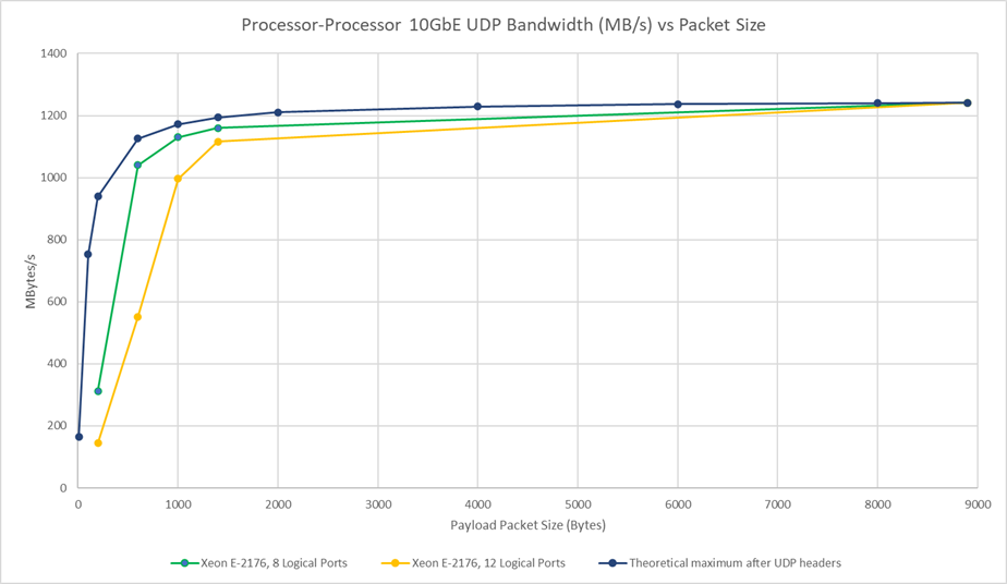
UDP link performance (10GbE) with E-2176 processor
This testing shows the impact of packet size on inter-processor UDP bandwidth. The graph includes a limit series, showing the theoretical maximum bandwidth achievable based on the impact of the UDP/IP headers/overhead. The other two series are based on testing with 8 logical ports and 12 logical ports. 8 logical ports being used for the transfer is optimum for this configuration because the Xeon E-2176 processor has 4 cores and 8 threads. If there is only a single logical port, then the performance is likely to be limited to whatever a single thread in the processor can handle.
Tests were performed with a variety of packet sizes, from 200 to 9000 (maximum jumbo frame).
White paper processor vs packet size
Although UDP is a much simpler protocol than TCP/IP, the processor must deal with the protocol directly, so small packet sizes can have a large impact on the achievable bandwidths. If there are a small number of logical ports, then some of the Ethernet FIFOs/buffers and processor threads cannot be used (for the single threaded application), further limiting the performance.
TCP/IP link performance (10GbE) – C3000 and E-2176 processors
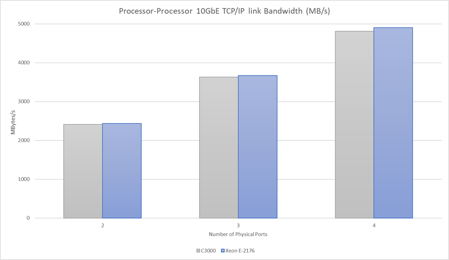
Processor link bandwith graph
The above chart shows that for both processors (and associated NICs), the TCP/IP overhead is minimal. Link utilization figures are over 96% even with 4 physical ports active simultaneously. This is only possible because offload engines are dealing with the TCP/IP protocols.
Some key takeaways are that packet size has a significant factor on link bandwidth with UDP, and that TCP/IP offload engines allow TCP/IP bandwidth to be extremely competitive despite the large packet header sizes, and the complications of the protocol implementation.
2.4.5 NFS, SAMBA, iSCSI, and other High Level Protocols
Ethernet also supports a wide range of other high level protocols such as NFS, SAMBA, etc. Common for these protocols is unpredictable timing and high CPU overhead, which typically makes them unsuitable for streaming data applications.
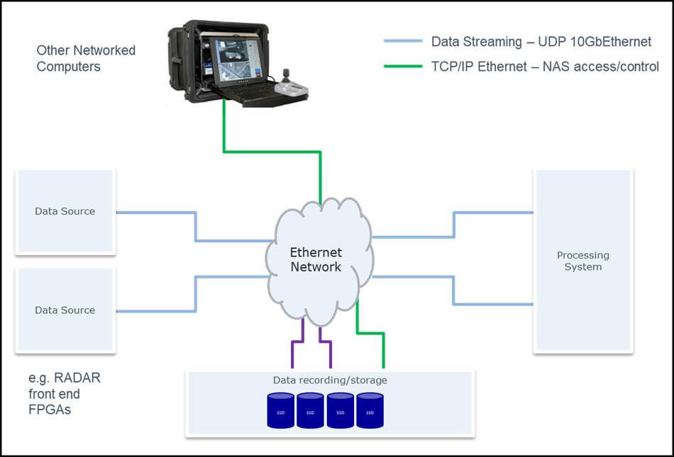
However, a major benefit of using Ethernet for data streaming is the possibility of utilizing such higher level protocols for data management and post processing. For example, consider a Radar system, containing a radar front end (primary data source), a processing system, an operator display and a network attached mass storage device, all connected over a switched 10Gb Ethernet network. RAW data can be transferred from the Radar to the processing device using UDP or TCP/IP protocol for high bandwidth and low latency. This unprocessed or partially processed data typically consists of a massive data burst of several gigabytes of data containing one Radar pulse, transmitted over a few milliseconds. The data stream then goes idle waiting for the next pulse and consequent data burst. During this pause in data transfer, the processing system analyzes the data and generates a small amount of processed data representing the result. The result can be transmitted to the operator display as a video transport stream embedded in UDP datagrams. For logging and tracking purposes, processed data can also be saved to a NAS using NFS or SAMBA protocols.
White Paper 10GbE vs sFPDP Graph3
One issue with these high level protocols for real time data transfer is timing uncertainty. Typically TCP/IP is used as a lower layer, with its advantages of guaranteed packet delivery, resend, etc. The higher level protocols implement further protections, for instance around shared resources and authentication. Timing is not necessarily predictable or repeatable. E.g. if a CRC check fails, and resend occurs, then transfer timing becomes effectively non-deterministic.
3.
Serial FPDP
Serial FPDP is defined in the VITA 17 standard, with the latest version being VITA 17.3. It defines a high bandwidth dedicated link for real time data flow to occur without the use of shared busses.
3.1 History and VITA 17 standard development
Front Panel Data Port (FPDP) originated to provide a high bandwidth inter-board data flow between VME cards without needing to share use of the VMEbus backplane connectivity. This dedicated bus could guarantee data transfers without interrupts. It was designed for unidirectional data flow, with very little signaling in the other direction.
The VITA17 standard was ratified in 1998. High bandwidth data was accompanied by sideband signals which were typically used as markers, or frame demarcation. This original Front Panel Data Port standard also defined the connectors to be used, with a multi-drop ribbon cable also being defined.
With the advent of high speed serial signaling, the FPDP standard evolved to serial Front Panel Data Port (sFPDP), standardized as VITA17.1, ratified in 2003. sFPDP achieves most of the same aims as the original FPDP:
- High bandwidth
- Dedicated connectivity avoiding the possibility of data flow being interrupted by other users typical of a shared bus
- Capability to mark specific points in the data flow
- Easy interfacing for FPGAs (vendor independent)
- Very low latency real time data flow
- Unidirectional connectivity supported, with option for flow control with return channel
When compared to FPDP, serial FPDP adds the ability for long and very long connection distances, with operation as either Electrical or optical high speed serial connections being supported. Serial FPDP couldn’t continue the original FPDP multidrop capability, but it introduced a copy mode of operation for a receiver – so that the received data would be retransmitted with very low latency onto a separate connection for downstream receivers. Copy/Loop mode allowed for flow control to be performed without the return channel:

White Paper 10GbE vs sFPDP Graph4
The original release of VITA 17.1 (sFPDP Gen 1.0) supported three different bit rates up to 2.5Gbaud, and 8b/10b encoding (i.e. data flow could occupy up to 80% of the bit rate). Galleon extended the use of sFPDP from the 2.5Gbaud maximum defined in the standard up to 4.25Gbaud. The VITA 17.1 standard was extended up to 10Gbaud in the most recent update, ratified in 2015.
Over time, serial FPDP bandwidth became a limiting factor in its selection, and the VITA 17 committee worked to create an update to the standard to support higher bandwidths. Since 2015, the VITA 17.1 standard supported link rates up to 10Gbaud; however, not many equipment and board vendors supported those higher bit rates because sFPDP Gen 3.0 was planned for release shortly afterwards. After a long process of discussion including bypassing a Gen 2.0 version, the VITA 17.3 standard was ratified in 2018. This sFPDP Gen 3.0 standard adds the following enhancements to improve data flow bandwidths:
- Bit rates unconstrained – link rates up to 25Gbaud operation are mentioned
- Channel bonding options (constrained by hardware functionality implemented) with maximum of 256 lanes
- Encoding with 64b/67b to achieve over 99% link utilization – using the industry standard Interlaken Framing layer
Serial FPDP Gen 3.0 also added some optional reliability enhancements – CRC protection for all status and control signals, and a retransmit mechanism for user data blocks were both introduced.
3.2 Physical media and range
Because serial FPDP is designed to use standard SERDES (Serialiser/Deserialiser) hardware connections, it is suitable for using any connectors designed for high speed serial differential pair signals. Care must be taken to ensure that signal integrity is maintained.
For long distance connections, low weight, and electrically noisy environments, optical fiber is typically used.
sFPDP Gen 1.0 standard (VITA 17.1) made recommendations for physical media, based on the FibreChannel standards. sFPDP Gen 3.0 makes the same recommendations, for backwards compatibility reasons.
3.3 sFPDP benefits for data streaming
Most of the sFPDP benefits for data streaming are related to the fact that it is fundamentally point-to-point (or single transmitter, multiple receiver). Therefore there are no requirements for headers with address information, etc. As a result, the protocol is very easy to handle in an FPGA. Similarly, there is very little loss of bandwidth for overheads.
Note that the latest version of the sFPDP standard (VITA 17.3) adds an option for packet verification and resend. This mode of operation obviously sacrifices much of the simplicity of serial FPDP in order to make the link more reliable. Many serial FPDP implementations will continue to operate without using this resend capability to save FPGA resources and maintain real time transmission of data. Even without retransmit, sFPDP still supports error detection, which can be used to identify which packets were dropped, even if the data is lost.
Key benefits of sFPDP for data streaming
- Low overhead – address information is not necessary
- Special character sideband information transmission alongside the payload data are included in standard sFPDP frames
- This is partially offset by the less efficient coding scheme (64b/67b) for sFPDP VITA 17.3 compared to the 64b/66b used for Ethernet (e.g. 10GBASE-SR)
- Deterministic timing – FPGA implementations allow extremely accurate and repeatable timing on data transmission/receipt including when using separate hardware for transferring parallel streams of data
- Accurate timing for playback (for recording applications)
- Flow control support without loss of data (or the need for retransmission)
- Extremely high bandwidth – channel bonding added in VITA 17.3 (sFPDP Gen 3.0)
- sFPDP Gen 3.0 uses the industry standard Interlaken encoding (64b/67b), allowing the use of standard blocks within the target FPGAs
- CRC checking of all control and status signals
- Error detection for data payloads, and option for guaranteed delivery – retransmission
- There is a small header and packetization overhead, but it has a minimal impact on performance for high bandwidth data streaming applications
Bandwidth for sFPDP depends on the baud rate being used. It also depends on whether the sFPDP link is based on VITA 17.1 or VITA 17.3 implementations. VITA 17.1 uses an 8b/10b encoding, whereas VITA 17.3 uses 64b/67b. VITA 17.1 defined a list of specific baud rates which could be used, whereas VITA 17.3 does not specify (or limit the bit rates). The table below provides maximum bandwidths achievable with the 2 versions of the standards (assuming that retransmission does not occur).
| sFPDP bit rate vs realizable data bandwidths per lane (Mbytes/s) | 2.5Gbaud | 4.25Gbaud | 8.5Gbaud | 10.0/10.3125Gbaud |
|---|---|---|---|---|
| VITA 17.1 (8b/10b encoding) | 247MBytes/s | 420MBytes/s | 840MBytes/s | 988MBytes/s |
| VITA 17.3 (64b/67b encoding, Interlaken link layer) | 296MBytes/s | 503MBytes/s | 1.0GBytes/s | 1.23GBytes/s |
| 2x VITA 17.3 links channel bonded | 592MBytes/s | 1.0GBytes/s | 2.0GBytes/s | 2.46GBytes/s |
With 2 lanes channel bonded the bandwidths are doubled, and if 4 lanes were bonded, the bandwidths would be quadrupled (e.g. 4.8GBytes/s with four 10Gbaud VITA 17.3 sFPDP links)
3.3.1 sFPDP framing overheads
For completeness of a comparison between Ethernet and sFPDP, the packet header overheads are listed here:
VITA 17.1
- 24 bytes header with max 2048 byte payload. (512/518 usable)
VITA 17.3
- sFPDP framing: 24 bytes header with max 32768 byte payload. (4096/4099 usable)
- Interlaken framing: 32 bytes header with fixed 16352 byte payload. (2044/2048 usable)
These framing overheads are included in the bandwidth figures shown above (small enough to be hidden by rounding accuracy).
4.
Example application
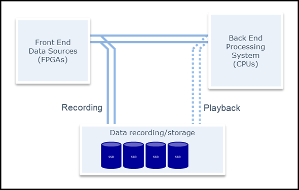
In this example application, a processing system has an FPGA based front end, and a CPU back end. The data consists of two logical channels, tightly linked to each other.
The data being streamed between the two needs to be recorded to support ongoing design and verification work on the back end processing algorithm. Playback of the recorded data must support similar signal timing to the original streamed data, including timing accuracy between the two channels.
During recording, the outputs from the data sources are also sent to the data recording system. This demultiplexing may be performed in the data sources (driving the same data to two outputs) or using switches or 1:2 buffering. During playback, the outputs from the recording system are plugged into the processing system instead of the real data from the front end.
White Paper 10GbE vs sFPDP Graph5
Without the recording requirement, 10GbEthernet with UDP would probably be the best solution (section 5.1.1 review below), provided that the system has reliable link connectivity (so the link error rate is very low, and resend or guaranteed delivery is not required).
However, the recording and accurate timing playback requirement really enforces the need for a recording solution based on FPGAs. Recording systems with sFPDP always use FPGAs for the interface. Galleon sFPDP recorders also implement an accurate playback capability
- The Galleon sFPDP uses time stamps captured by the front end of the FPGA on receipt of data. Those timestamps are used during playback for the FPGA to delay transmitting data until the correct time.
The same technique as described above for the Galleon sFPDP recorder may be used for implementing UDP recording and playback. Playback with accurate timing would require that the link is always available because any other activity on the link would cause a delay to data transmission. But in a simple point-to-point topology as used in this application, the 10GbEthernet link should always be available.
5.
Summary and Conclusion
5.1 Summary comparisons
The table below compares each of 3 possible data streaming protocols/formats.
- sFPDP VITA 17.3, assuming 10.3125Gbaud link rate
- 10Gb Ethernet using UDP
- 10Gb Ethernet using TCP/IP
2 Note: sFPDP VITA 17.3 with support for retransmit sacrifices many of the sFPDP advantages – e.g. simple implementation in FPGAs, easy handling for processor interfaces, and guaranteed timing.
3 This table assumes Processor based UDP interfacing. An FPGA based UDP interface could provide accurate playback timing, using the same techniques as for sFPDP recording and playback.
5.1.1 Suitability for different applications
The table below compares each of the same 3 data transfer channels for some specific operations, considering how well suited each channel is to the task at hand.
5.2 Conclusion
The choice of physical and protocol channel for data streaming depends heavily on the requirements of the application.
Serial FPDP still holds advantages over Ethernet protocols for certain applications, e.g. FPGA to FPGA data streaming with real time requirements. But Ethernet holds many advantages with its ubiquitous use in computing, networking, and its huge supplier base (when compared to serial FPDP). Ethernet links can also support multiple different data transfer simultaneously over the same physical links (bandwidth permitting). A designer who ensures that there is sufficient bandwidth margin available in an Ethernet network will provide some useful capacity for later upgrades.
For very high bandwidth data streaming applications from FPGA to CPU, 10GbE UDP performance improves when sending multiple logical streams over a single link (ideally, one logical stream per processor thread), whereas sFPDP is better suited to a single data stream per physical link.
6.
Feedback and References
6.1 Feedback
Any questions or comments to the contents are welcome and appreciated. Please contact Hugh Tarver, htarver@galleonec.com or send your feedback to info@galleonec.com
6.2 References
List of references used in document.
www.vita.com Source for VITA 17.3 sFPDP standard
https://www.ieee.org/ Source for Ethernet standards (IEEE 802.3 and sub-standards)
https://www.ieee802.org/3/ IEEE 802.3 (Ethernet) working group pages