

Abstract
This document describes the cooling requirements of rugged electronic enclosures.
It is intended to raise awareness of some thermal design aspects of installing electronics enclosures (LRUs) into a system.
1.
Cooling Concepts
This white paper covers cooling techniques for rugged electronic enclosure being fitted into larger systems. It does not cover the thermal design techniques used inside those enclosures.
Rugged electronic enclosures are designed to be cooled in particular mechanisms, and it is important to use the cooling method which the product has been designed to use.
Cooling can be achieved in a number of ways:
- Conventional convection cooling where heat is exchanged between the surrounding air and the electronics enclosure either by passive air flow (passive convection cooling) or assisted by fans (forced convection cooling)
- Conduction cooling where heat is transported from the electronics enclosure to the surroundings by means of mechanical transport (typically metal to metal connection). Conduction cooling can be further enhanced by means of heat pipes, thermal conductive pads or paste, etc., to lower the thermal resistance between various materials and help distribute heat to a larger surface area or to avoid hot-spots in the design.
- Liquid cooling, either indirect by circulating a coolant in internal pipes in the design, or spraying or submerging the electronics in a cooling liquid.
Different cooling systems for Galleon Products
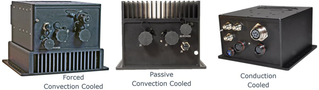
Figure 1, One LRU design with three different cooling options.
The system level thermal design must be adopted to the cooling method of the Line Replaceable Unit (LRU). For instance, a conduction cooled LRU cannot be operated when mounted on top of a thermal insulator, and a forced air-cooled product cannot be operated with air flow blocked at the fan inlet or outlet.
The fundamental laws of physics applies also to thermal designs; i.e. energy cannot appear or disappear – All energy injected into the system must be removed at the same rate for the temperature of the system to remain constant.
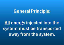
Figure 1: General principle of power dissipation
The above principle means that if a rugged electronics enclosure dissipates 100W of power, then 100W of heat will need to be transported away from the system.
In some cases, the power dissipation is low enough that detailed thermal design is not required. However, some care should always be applied when designing an installation for electronics to ensure that the heat from the product is dissipated away from the product and into the environment.
Also note that conduction cooling can be effectively combined with air cooling – e.g. with a conduction-cooled enclosure with external fan assisted cooling (also refer to the illustration in section 1.3.1).
1.1 Thermal design basics
Thermal design relates to the process of creating an installation which ensures that the product is kept within its specified temperature range.
For air cooled products, this is relatively simple – ensure that the air which is passing over the product or through its fans is below that temperature. For conduction cooled products, the thermal interface is the conduction surface (typically specified as the baseplate temperature). Therefore, some additional analysis is required to compare that thermal interface to the air temperature, for instance.
Thermal design needs to take account of the properties of the materials (e.g. thermal conductivity for conduction cooling, or air pressure for air cooling). These are explained in more detail in the following sections. The design must also consider how the power will be dissipated after being taken away from the electronics – the heat generated by all electronics enclosures should be dissipated into the surrounding environment.
1.2 Conduction Cooling
Conduction cooling is used when the primary thermal path for the product is through a defined external surface, typically the base plate or similar thermal interface. The thermal interface must be flat, and designed to be mounted against a flat surface of thermally conductive material. The figure below shows a simple representation of a conduction cooled enclosure:
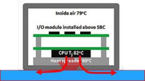
Figure 2: Conduction cooling for rugged electronics enclosure
Conduction cooled electronics enclosures are specified by the temperature of their thermal interface (baseplate or similar). This is not the same as the air temperature. In fact, depending on the thermal design of the installation, the thermal interface could be considerably higher than the temperature of the surrounding air.
Although most conduction cooled enclosures do have some thermal dissipation into the air (e.g. on the 5 faces of the box which are not the baseplate), this is a small enough fraction of the total heat dissipation that it is reasonable to ignore it for most thermal analysis.
The below table provides some simple data of common materials (pure material thermal conductivity). Note that although air is a very poor conductor, although it can still be used to transfer heat, but only when moving – it absorbs the heat energy from surfaces that it passes over, and when the air moves, it takes the heat energy with it. The other materials listed are not used in the same moving mechanism, so their thermal conductivity is the critical factor in selection of suitable materials.
| Material | Air | Aluminum | Copper | Stainless Steel | Cast Iron | Carbon Steel |
|---|---|---|---|---|---|---|
| Thermal Conductivity (W/mK) at 25oC | 0.0262 | 205 | 401 | 16 | 55 | 54 |
1.2.1 Conduction cooling thermal analysis
All thermal analysis is heavily dependent on the data used. For instance, if the thermal resistance of the material is incorrect, then the thermal analysis will produce incorrect information. However, rough estimates can be relatively easy to produce, as shown below. These examples are not intended to replace a full thermal analysis of a system, but they do give some idea of the principles behind heat transfer.
The thermal conductivity of most materials is relatively easy to obtain, expressed as W/mK (Watts per meter Kelvin). So, for a simple example, consider 100W of power passing through a 1cm length of Aluminum with cross sectional area 100cm2 (10cmx10cm), or 0.01m2. The temperature difference across the material for this example is calculated as follows:
∆T = (Power x distance) / (k x Area) = (100 x 0.01) / (205 x 0.01) = 0.49oC (or Kelvin)
k is the thermal conductivity – for simplicity, the figure (205) for pure Aluminum is used for k. Note, in comparison, the figure for still air is only 0.0262 W/mK
Note that heat travelling through a thin plate is much less efficient. The temperature difference for 100W through a 1cm length of Aluminum with cross section 5mmx10cm is nearly 10oC.
When the heat needs to transition between two mated surfaces, then the thermal resistance of the material (or air) in the gaps needs to be taken into account. In all cases, the temperature drop across the material is effectively calculated by multiplying the thermal resistance by the power being dissipated across the material or interface.
The principle of conduction cooling thermal analysis is that the heat will be conducted away from the power generating components/enclosures to areas where the power can be dissipated into the environment (air/liquid/etc.). That can only happen if the installation is able to pull the heat away from the cold plate. Some examples of this are described later in this document.
1.2.2 Thermal conductivity between two surfaces
When two metal plates are assembled, there are gaps caused both by a lack of surface flatness and by surface roughness, represented in the figure below.
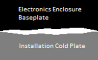
Figure 3: Air gaps between mated surfaces
Still (non-moving) air is a very poor heat conductor, so the gaps created by these factors cause a problem for cooling by effectively reducing the cross section of the contact area between the two materials.
Ensuring that the enclosure is held securely in place will apply pressure to the gap between the baseplate and the cold plate, which will help to reduce these gaps.
Other mitigating actions could be:
- Remove thermally resistive coating from the metalwork
- Use thermal interface materials (TIM), which fill the air gaps and has much better thermal conductivity than air
Note, however, that these gaps only contribute to a thermal resistance across the interface. If the mating faces have a large area, then the temperature drop could still be very small.
The design of the installation should take account of the conductivity and surface are of the thermal interface between baseplate and cold plate. The designer should decide whether any mitigating actions are necessary. One option is to use Thermal Interface Materials (TIMs), such as thermal paste or gap pads, to fill these thermally inefficient air gaps.
1.1 Air Cooling
Air cooling relies on the ability of moving air to transfer energy from one place to another. Although air is a poor conductor of heat, heat energy in metal will transfer into the air close to the surface. If that air is moving, then the heated air will effectively take away the heat energy. It is worth noting that this is only effective if there is somewhere in the larger system which can exchange the heated air for fresh/cold air. Without that ability, the effect would only be similar to a fan assisted oven.
Air cooling is effective at the surface of the metal, so it is common to enhance the surface area for heat transfer as much as possible with a heatsink design. Use of fins or similar achieve this aim, with the selection of the fin thickness and gap thickness being critical to the effectiveness of the design.
The design of the heatsink is a compromise between competing factors. If the fins are too thin, the heat cannot transfer to the ends of the fin very effectively. Similarly if the gaps are too thin, the air cannot travel through the gaps effectively. Therefore the heatsink is often designed to match the air capacity of the fans which will be used.
One advantage of air cooling is that the thermal interface is the air temperature, simplifying the system level thermal design task. Ensuring that the inlet and outlet vents are clear of obstructions and ensuring the heated air can be exchanged for fresh cold air, are all that is required.
However, air cooling is affected severely by altitude (air cooling is directly affected by air pressure), so many airborne applications don’t perform well with air cooled products (‘thin’ air at high altitude is much less effective at removing heat from the material that the air passes over).
1.3.1 Active/Forced Air Cooled Enclosures
When the enclosure includes the equipment necessary for moving air, then it is referred to as active air cooling. There are two main types of active air cooling, with distinct differences in terms of reliability in rugged systems.
Fans blowing air over the electronics and internal heatsinks
Fan blowing air over cooling fins attached to a sealed (conduction cooled) volume, all within a single enclosure.
Fans blowing air over electronics is standard practice in commercial and server grade electronics enclosures because it is an extremely efficient method for heat removal. However, the air can only be partially filtered, and with the air come particles (dust, moisture, fungus, etc.) which can damage the electronics. Even if the electronics components are coated (conformal coating or similar), the expected lifetime of the equipment is reduced, compared to keeping the cooling air flow away from the internal electronics, with a design like the one shown below.
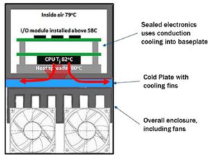
Active air cooling with sealed electronics
1.3.2 Passive Air-Cooled Enclosures
When an enclosure uses air cooling, but doesn’t include components for moving air, it is considered to be passive air cooled. This type of equipment typically has some fins or similar mechanics for increasing the surface area over which air would flow.
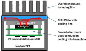
Figure 5: Passive air cooling with sealed electronics
One issue with this type of design is that the heatsink has to be designed for a particular air flow, which is not likely to be matched exactly by any real installation. For all passive air cooled installations, it is recommended that extensive temperature testing is performed to characterize the effectiveness of the cooling.
2.
Installation Options and Examples
This chapter provides some examples of cooling equipment and installations. Some of these are real installations, but all customer and program details have been obscured.
2.1 Cold Plates
Cold plates are designed to extract heat away from a hot surface i.e. conduction cooled LRU. In the simplest case, a cold plate is the surface that a conduction cooled enclosure is bolted to.
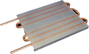
Figure 6: Example liquid-cooled cold plate
Liquid-cooled cold plates are designed to transfer heat much more effectively than conduction cooling.
2.2 Air Flow and Ventilation Example
One example of using separate forced air cooling around a conduction-cooled enclosure is shown in the following pictures. This is not a recommended practice but gives an example of a solution where the thin material of the installation plate and the lack of other heat transfer mechanisms force some non-standard design techniques.
Note that the conduction cooling installation plate in this example is not sufficient to extract the heat away from this electronics enclosure on its own (conduction cooling through thin plates is not efficient). Therefore pins/fins underneath the plate are used to enhance the transfer of heat into the air, and a large fan is used to force air around the enclosure and the installation cold plate.
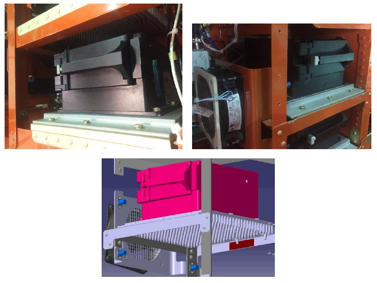
Figure 7: Example conduction-cooled installation with external air cooling
3.
Summary and Conclusions
3.1 Summary
The purpose of this white paper is to raise awareness of the need for thermal design when installing electronics enclosures into rugged systems. Increased awareness should help designers to avoid some of the common pitfalls.
Active air cooling is perhaps the simplest method of cooling as regards the installation thermal design, but it has associated problems (fan reliability and maintenance, particles contaminating electronics, and increased size of enclosures compared to conduction cooled). Also, active air cooling often has a restricted high-temperature specification available (with fixed fan options).
Conduction cooling provides the physically smallest enclosures, with the least weight, but it is essential for the installation to be designed to transfer the heat away from the enclosure.
4.
Feedback and References
4.1 Feedback
Any questions or comments to the contents are welcome and appreciated. Please contact Hugh Tarver, htarver@galleonec.com or send your feedback to info@galleonec.com
4.2 References and other useful material
Some analysis of conduction cooling across mated materials:
A useful page with thermal conductivity figures for common materials: https://www.engineeringtoolbox.com/thermal-conductivity-d_429.html
Some details around thermal interfaces and peltier coolers: https://customthermoelectric.com/tech-info/install/txl-teg-installation.html