
Abstract
This document describes data security techniques for Data at Rest (DAR) in embedded systems, including hardware, software, and self-encrypted drive (SED) encryption methods, as well as secure erase for permanently deleting the data. The most important benefits and concerns with the various methods are discussed. Certification options including Common Criteria (CC) and Commercial Solutions for Classified (CSfC) are also discussed.
1.
Introduction
Data is an extremely valuable resource, and for many applications, it needs to be protected. Three types of data are generally described:
- ‘Data in Use’ is being actively processed inside a computer system. It may be in dynamic RAM, computer registers, or processing engines.
- ‘Data in Transit’ is being sent between different computer systems typically over a network and/or datalink connection.
- ‘Data at Rest’ is stored on non-volatile disk drives – in many cases, the drives can be physically removed from the computer system concerned.
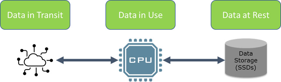
Data at restFigure 1, Data at Rest (DAR).
This paper only considers Data at Rest (DAR).
System integrators and end users have multiple reasons for considering protection of stored data. Program requirements or best practices for data protection can determine which level of Data at Rest protection may be required or needed. Often data security will require integration of multiple systems and a change of operations to protect both the data and the key to access the data.
Modern rugged embedded computers and servers used in aerospace and defense systems are required to operate in the harshest environments. These systems may be on platforms that are unmanned or unattended in operation which can increase the need for data security but also increases the complexity of the system since there are no local operators. What has worked well in the modern office may not translate to data security success on the battlefield.
This white paper will take a closer look at the various options for securing Data at Rest in rugged embedded systems. The white paper considers various methods for encrypting Data at Rest, as well as details of the options for erasing that data. Encryption and secure erase can be used separately or together depending on the needs of the application and program.
Note that Galleon Embedded Computing products are available with a wide range of data security options, up to and including top secret. Therefore, this white paper does not seek to push any one solution. Instead, it aims to provide information on the advantages and disadvantages of the different approaches. The particular solution best suited for an application can be influenced by data security requirements, operational requirements, location of equipment, data rates, and other requirements.
2.
Case Study – NATO AGS
The Alliance Ground Surveillance program is described on this NATO web page: https://www.nato.int/cps/en/natolive/topics_48892.htm
With a Unmanned Aircraft System (UAS), there are always concerns about what happens to the data if the UAS should be lost or diverted to an uncontrolled location during a mission. This was just one of the security aspects within the data recording and management requirements for this program.
Galleon Embedded Computing was able to provide a COTS solution which satisfied those requirements.
The Galleon Embedded Computing Small Form Factor XSR Network Attached Storage (NAS) with Hardware Full Disk Encryption was selected due to the ease of use, small size, security features, and the large storage capacity available. A COTS solution that provided the entire solution in a small conduction cooled package made installation and integration easier onto the aircraft.
The XSR Secure NAS can provides multiple functions on a platform such as the NATO AGS UAS. With multiple data storage options and keying options, the system can be used to not only as a secure data recorder and storage system, but also as a network boot device connected to other critical systems.
The XSR Secure NAS provides multiple Gigabit Ethernet ports and optionally 10GbE for a wide range of common interfaces for connectivity to other systems. Using common a interface such as Ethernet, the NATO AGS program is able standardize on what is the industry standard for computer connectivity. Standardization is advantages as it allows for better long-term support and life cycle management.
The high capacity XSR Removable Data Module (RDM) is protected with a Hardware Full Disk Encryption solution. The XSR RDM allows for tool free removal and swapping of high speed / high capacity storage up to 80 TB is size. For moving data to and from the XSR RDM for data analysis or mission preparation, an offload server is used with a compatible hardware full disk encryption module.
Galleon Embedded Computing has been able to provide a full solution to the NATO AGS program.
3.
Key Terms
This section defines and explains the most common terms used throughout the white paper.
AES: Advanced Encryption Standard – A block cipher
Authentication: Enabling/unlocking an encryption engine so that the encrypted data can be accessed.
Brute force attack: An attempt to access encrypted data by guessing the 256 bit key
CSfC: The Commercial Solutions for Classified program is a US government program for approval of commercial products to be used in solutions protecting National Security Systems (NSS) data.
CC: Common Criteria for Information Technology Security Evaluation is the technical basis for an international agreement, the Common Criteria Recognition Arrangement (CCRA). This arrangement is that each of the Member countries will have independent licensed laboratories for evaluation of any product’s security properties in line with all of the other Countries. There are currently 17 Certificate Authorizing Members, and another 18 Certificate Consuming Countries.
DAR: Data at Rest refers to inactive data which is stored in any digital form.
DEK: Data Encryption Key – This key is used to encrypt/decrypt data to/from the drives
EDEK: Encrypted DEK – This is an encrypted version of the DEK (see above)
FIPS 140-2: Federal Information Processing Standard 140-2 is a US government standard which is used to approve cryptographic devices and modules. Note: an updated version, FIPS 140-3, was released in 2019 – it is expected that crypto devices will be certified to the new revision.
HWFDE: Hardware Full Disk Encryption
KEK: Key Encryption Key – This key is used to encrypt/decrypt the EDEK (see above), typically generated from username/passcode authentication data using PBKDF2 (see below)
NAS: Network Attached Storage
PSK: Pre-shared Key – a known encryption key – for secure data module portability
PBKDF2: Password Based Key Derivation Function 2 – a key derivation function designed to mitigate the lack of entropy in username/password combinations compared to the 256-bit key
RDM: Removable Data Module
SSD: Solid State Drives use flash memory arrays to provide storage capacity.
SWFDE: Software Full Disk Encryption
Symmetric encryption – The use of the same encryption key for encryption and decryption. Asymmetric encryption, in contrast, uses a combination of keys (e.g. private key and public key) to encrypt the data – typically for use with secure links.
4.
Encryption
Encryption protects data without erasing it. E.g. when transferring a Removable Data Module (RDM) from a deployed recorder/NAS to a base station, the data is secure but still intact.
There are several types of encryption for Data at Rest. This paper will discuss Self-Encrypting Drives (SED), inline hardware full disk encryption (HWFDE), and software encryption, including software full disk encryption (SWFDE). Note that SEDs are a form of hardware encryption, but the term ‘hardware encryption’ is used in this paper specifically for the separate inline hardware encryption solution, in the path to the SSDs.
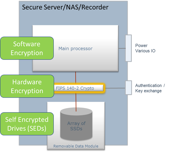
Figure 2, Encryption mechanisms
All three methods use standard encryption algorithms (typically, AES-256).
Note that AES is a block cipher, meaning that it encrypts blocks of data. Additional protection is required for Data at Rest to ensure that repeating patterns in the unencrypted data don’t get encoded with identical encrypted data patterns. One widely used scheme which protects against this risk is AES-XTS (sometimes called XTS-AES).
4.1 Comparison of encryption mechanisms
- Self-Encrypted drives (SEDs): Encryption is available as a part of the function of SSDs (Solid State Drives). SEDs come in many different versions including certified/approved versions and versions which comply with commercial standards like Opal. With Opal based SEDs, the encryption key is typically created and stored (encrypted) inside the SSD and cannot be exported. Unlocking Opal based drives is relatively simple, and typically only requires a password to unlock. With certified/approved SEDs, options for key handling vary, so they are more similar to the inline encryptors described below, except that the encryption device resides inside the SSD.
- Hardware Full Disk Encryption: Bulk encryption devices are used in the path between the computer system and drives. Various encryption key handling and unlocking schemes are available. Hardware inline encryption may be built into the same product as the removable drive. There are also some external inline encryptors, some of which are certified to high security levels. They function the same way and have similar options for key handling. The only differences are that they are separate enclosures, and they may differ on levels of certification/approval.
- Software Encryption: Data being sent to the drive is encrypted by software running on the computer. Typically, the key is created in software and stored (encrypted) in a partition on each drive, although other options are also available.
| Mechanism | Advantages | Disadvantages |
|---|---|---|
| Standard (e.g. Opal) Self-Encrypting Drives (SEDs) | Easy to use Cost effective | Key and encryption devices are inside the SSD Typically not certified, other than the AES algorithm Typically just 1 password |
| Certified/approved SEDs | These vary with the specific device – some operate similarly to Opal based SEDs, while others are more like the hardware full disk encryption option described below. Certification is normally related to the depth of testing and verification of the key handling as well as the encryption algorithms, rather than the functionality itself | These vary with the specific device – some operate similarly to Opal based SEDs, while others are more like the hardware full disk encryption option described below. Certification is normally related to the depth of testing and verification of the key handling as well as the encryption algorithms, rather than the functionality itself |
| Hardware Full Disk Encryption (HWFDE) – inline hardware encryption (internal and external) | Uses certified crypto Certifiable (Common Criteria) Dedicated key exchange port with dedicated processor, so the key and/or authentication is never exposed to the main processor domain | Complex system integration and user interaction Tied to single storage topology (ie, SATA at this time) |
| Software Encryption – including Software Full Disk Encryption (SWFDE) | Certifiable (Common Criteria) Separate encryption for partitions | Key stored inside SSD Careful integration for keying and authentication management |
Table 1, Encryption mechanisms comparison
Note that although software encryption does require some processor cycles, the impact on performance is typically minimal – most processors include encryption/decryption offload engines, so there is not much load on the main processor engines. Therefore, processor performance is not listed above as a disadvantage.
4.2 Encryption key handling
Data at Rest encryption involves an encryptor of some sort encrypting and decrypting data as it is written to and read from the disks. The diagram below shows this concept and introduces the acronym, DEK, as Data Encryption Key.
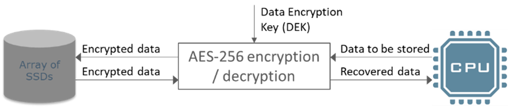
Figure 3, Data Encryption Key (DEK)
AES-256 is extremely effective at protecting data from brute force attack, so the only way that the data could become accessible is if the data encryption key (DEK) is accessed by an attacker. Therefore, the selection of the key handling mechanism is critical to the overall security of the data. In most cases, the more secure mechanisms add more system complexity. There are 2 fundamentally different approaches – either transfer the key itself, or store the key encrypted and use authentication to decrypt the key.
In some systems, the DEK is provided to the system at power up. However, securing the DEK can be complicated, so many systems use an alternative method which involves storing the data encryption key on the platform or disk. To secure the key from simple attack, it is stored in an encrypted form. The diagram below shows this concept and introduces the acronyms, EDEK, as Encrypted Data Encryption Key. It also introduces the acronym, KEK, as Key Encryption Key, which is the key used for the encryptor converting the EDEK into the DEK.
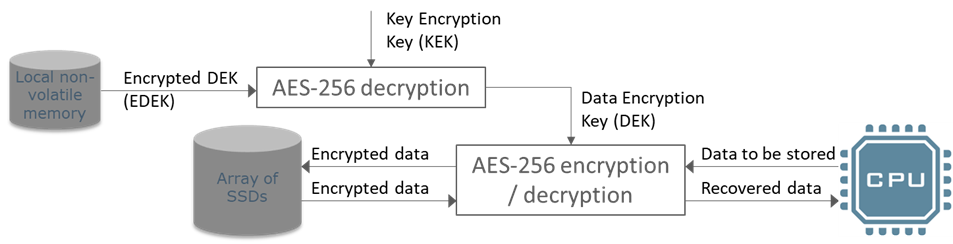
Figure 4, Encrypted Data Encryption Key (EDEK)
The Key Encryption Key (KEK) is also used for generation of the EDEK (by encrypting the DEK). Generation and handling of the KEK is described in section 4.2.1 below.
The following table gives an overview of the alternative methods available for key handling and/or authentication at startup.
Encryption key is transferred directly
Nothing stored locally, no username/passwords potential weakness
| # | Key handling method | Advantages | Disadvantages |
|---|---|---|---|
| 1 | Physical token | Ease of use | Token management and logging Unmanned Systems require a virtual token or could be exposed if the vehicle is lost Complex to integrate multiple secure systems on a platform that all have unique tokens |
| 2 | Sent over secure link | Centralized key management – the key is not stored locally in non-volatile memory in any format | The key must be available in unencrypted form at the far end of a secure link The link must be secure |
Encryption key is pre-shared[2], and stored locally in encrypted form (EDEK)
Authentication required to decrypt the key
| # | Key handling method | Advantages | Disadvantages |
|---|---|---|---|
| 3 | Authentication data entered manually (keyboard or local connection) | Can be used in isolation - no link is required from outside the platform | Inconvenient for use with remote vehicles (e.g. UAVs) Username/password to be remembered - reduced randomness/entropy |
| 4 | Authentication data sent over secure link | Username/password can be complex, increasing entropy | The link must be secure |
| 5 | Authentication data stored in local server, EDEK stored on the Removable data module (RDM) - automatic unlock at startup | Simplest method – removes system level complexity RDM data security is assured (when separate from server) Key is auto-generated and stored in the SSDs | Only secures the RDM when being transported Encryption key cannot be backed up or recovered if erased |
Table 2, Encryption key handling/authentication options
Physical tokens could also be used for authentication for when the key is encrypted and stored locally
[2]The concept of pre-shared keys is discussed below in section 4.2.2. Note that it is possible for options 3, 4 and 5 to be used with SSDs (which generate their own keys) as well as with pre-shared keys
4.2.1 Username/password schemes
Storing the Data Encryption Key locally may seem counterintuitive, but with AES-256 encryption, it is not a security risk in itself. However, authentication using username/password to unlock that key does carry some risk. The problem is that the username/password is likely to have less entropy (randomness) and/or has less length than the 256-bit key. Therefore, attackers could aim to guess the username and password combination instead of the 256-bit key itself. To mitigate this risk, various techniques are used to make such an attack more difficult. These include:
- Hashing – processor intensive non-invertible algorithms which deliberately take time to complete, reducing the number of username/password combinations which can be tried in any time period. The hash function is selected based on the time it takes – to provide strong protection but ensure that the delay for normal operation (when the correct password is entered) is relatively short.
- Adding a randomly generated ‘salt’ value into the algorithm which adds some additional entropy, and prevent common username/passwords from generating the same hash / key encryption key across multiple users or units
Restricting the number of incorrect guesses before requiring a time delay between attempts (rate limiting). Note – this only really helps if the attacker is not able to access the Encrypted DEK (see diagram below) - Anti-forensic data storage – splitting the encrypted/hashed encryption key in storage to make it more difficult for attackers to recover the encrypted key from partially erased or damaged storage
An example of the process used to protect username/password schemes is PBKDF2 (Password-based key derivation function 2), which combines hashing functions and salt to provide protection from username/password attack.
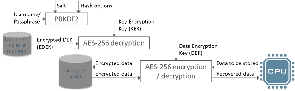
Figure 5, Key derivation function
4.2.1.1 Multiple users
With the above username/password schemes, it is possible for multiple different users to have their own username/password combinations for the same encryption key. The key handling solution just stores a separate encrypted key (EDEK), and salt for each valid username. There is still just a single data encryption key (DEK), so there is no reduction in security from brute force attack against that 256-bit key.
4.2.2 Pre-shared keys
A pre-shared key is one which is written into the device (in encrypted form) during commissioning of the system (typically in a secure location). The key is then available to be reused if required. The alternative is for the key to be auto-generated inside the device and stored (encrypted) inside the same device. In those systems, the key can typically never be exported.
With pre-shared keys, in the event a threat is present and the data is protected by erasing the stored key (EDEK), the data is not permanently lost and can be retrieved at a later stage when the threat is no longer present. In contrast, with auto-generated keys, if the EDEK is destroyed, then the data will be permanently unrecoverable.
4.2.3 Power loss or removal
If power is lost or removed, the DEK will be lost because it is only ever stored in volatile memory. Therefore, the Data at Rest will be secure. Any stored EDEK will remain intact because EDEKs are stored in non-volatile memory.
When power is reapplied, the DEK can be loaded again (whichever key handling mechanism is used), and the data will be accessible again.
4.2.4 Crypto erase
If a threat is detected, with many encryption systems, the DEK can be deleted/destroyed without needing to switch off power. This secures the data, and the DEK may be loaded again when the threat is no longer present, at next system start up.
However, as an added level of security, for systems which store the EDEK locally, it may also optionally be destroyed with a crypto erase. As mentioned above, with pre-shared keys, the EDEK may be reloaded when the threat is no longer active and the data may be recovered.
In contrast, with some encryption systems (e.g. Opal SEDs described below), crypto erase will erase both the DEK and EDEK. The EDEK is not a pre-shared key, so the data will be unrecoverable after such a crypto erase.
4.3 Self-Encrypting Drives (SEDs)
Note that this section deals with SEDs which implement encryption and decryption algorithms based on standards like Opal[1]. There are several examples of SEDs which implement more secure key handling algorithms necessary for Top Secret implementation (and below) – those are discussed separately in this document.
Many SSD vendors offer self-encrypting drives. Self-Encrypting Drives have built in encryption circuits as an integral part of the drive hardware and totally transparent to the end user when enabled. The methods and terminology used varies with the SSD vendor, but the fundamental process involves locking and unlocking the SSD.
In many cases, when there are no strict requirements for a high level of security and advanced key management, SEDs represent a simple and cost effective solution. Note that the SEDs used for this purpose should have validated AES algorithm implementations. Validation is available using the Cryptographic Algorithm Validation Program (CAVP) and collated in the Computer Security Resource Center (CSRC) run by the US government NIST group. For instance, this validation for hardware libraries used by some SEDs to validate against FIPS-197: https://csrc.nist.gov/projects/cryptographic-algorithm-validation-program/details?validation=12711
Self-Encrypted SSDs apply encryption/decryption as part of their standard operation (typically with very little impact on performance). Such encryption and decryption is unnoticeable to the user, as such. That’s because all data which is written to the SSD is encrypted, and all data which is read from the SSD is decrypted. The encryption key is auto-generated by the SSD.
The security functionality of the SEDs is enabled by locking and unlocking the device. Locking involves writing a special code (including passcode/passphrase) to the SSD using a special command. The SSD then creates a new key and stores it (encrypted) as well as using that key for encrypting/decrypting all data written to or read from the device. The device will then be inaccessible until it is unlocked (by writing the same code to the SSD, with a different special command).
Typically, this passcode/passphrase is not stored inside the SSD. Instead, it is used to encrypt/decrypt the encryption key in the SSD (randomly created inside the SSD) using techniques like the PBKDF2 algorithm described in the previous chapter, providing some additional data security.
Note: Not all drive vendors fully comply with the standards which define how to handle encryption and erase functionality (e.g. OPAL). Hence, an implementation can often become drive vendor specific and upgrading/changing drives may create compatibility issues.
[1] The Opal standard is published by the Trusted Computing Group
4.3.1 Authentication with SEDs
In commercial applications (e.g. laptops), the user is required to enter a password during the pre-boot initialization of the SSD (option 3 in Table 2 above). For many programs, especially with embedded computing, NAS, or recorder applications, this local authentication is not suitable. Therefore, Galleon provides alternative options, as described in options 4 and 5 of Table 2. Because the key is created inside the SED and stored there in encrypted form, the only options for authentication are based on password authentication to unlock the key. With most SEDs, there is only a single password which will unlock the drive. There is no option for multiple users to have separate authentications (described in the section on page 14 above).
4.3.2 Secure erase with SEDs
Note that many SEDs also implement secure erase algorithms, providing a dual layer of data security. Typically, if a threat is active, the encryption key is erased as well as the data. Data erase options are discussed in chapter 5.
4.4 Hardware Full Disk Encryption
For a higher level of security, Galleon offers advanced data encryption (AES 256-bit) implemented by a SATA to SATA Hardware Full Disk Encryption module that uses multiple inline crypto devices. These crypto devices have been certified to FIPS 140-2 and provide the data encryption and decryption capabilities.
The encryption module is a self-contained unit which handles key exchange fully transparent to the operating system and user application, as shown below.
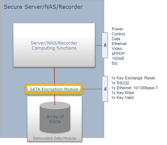
Figure 6, Hardware Full Disk Encryption (HWFDE)
4.4.1 Authentication with hardware encryption
With the hardware encryption solution, Galleon provides all of the options for authentication listed in Table 2, except for the physical token. In all cases, the RDM (Removable Data Module) can be removed and transported to a base station, with the same key available for the base station equipment as in the Server/NAS/Recorder.
When the key (DEK) is provided directly to the encryption module (option 2 of Table 2), the module provides secure link communiction through a dedicated Ethernet link, kept completely separate from the main processor. The data is safe unless the DEK is exposed.
When a pre-shared key option is used, the key is stored in the encryption module, using a key derivation function similar to PBKDF2 (described in section 4.2.1 above). The system is safe unless the authentication data is known (username/passphrase). Multiple (almost unrestricted number) different users can have separate authentication data with options also available to restrict each user’s access to specific RDMs.
When the RDM is extracted from the server, it is physically separated from the encryption hardware (where the key is stored), making it safe to transport to the final destination, where it is re-installed in a server or docking station with the same encryption hardware and pre-shared key for data retrieval.
Finally, because the encryption hardware is a part of the computer system, it is independent of the disk selected and will work with any SSD installed in the system. This allows for future upgrades to the latest SSD technology and capacity with no requirements to stay compatible with the encryption functionality embedded in any particular SSD. Further, tailored storage media can be used depending on the application. For example low cost commercial grade SSDs for lab and development use and high end military grade SSDs for deployed missions will all be supported by the same encryption hardware.
Note: At the time of writing, the only certified encryption devices for inline encryption are based on SATA connections. Therefore, it is only currently possible to provide inline hardware encryption module based on SATA, not for NVMe drives.
4.4.2 Comparison with Self-Encrypted Drives
The Galleon hardware encryption solution uses FIPS 140-2 certified crypto devices, whereas Opal based self-encrypted SSDs only have certification related to the correctness of the algorithm.
The hardware encryption module also provides additional data security compared to self-encrypted SSDs because the encryption key is not stored inside the disk and the encryption engine is inside the computer system, not inside the SSDs. With self-encrypted drives, both the key and the encryption engine reside inside the SSD.
Authentication is very similar to self-encrypted drives for the case when the passcode is sent over secure link, although even then, the encryption module has an advantage, because the Ethernet link used is dedicated to the microcontroller which is dealing with the key management, rather than the general processor (which will also deal with functionality unrelated to authentication).
Finally, the inline hardware encryption allows the system to use any qualified SSD at the end of the link, whereas encryption based on SEDs are typically tied to a particular SSD vendor.
4.5 Software Encryption
Software encryption for Data at Rest is widely used in the commercial world, with a simple username/password or fingerprint ID authentication at power up of the computer. This type of functionality is also available for more secure applications, and it can also be used alongside hardware encryption to enhance the security of the data. The two layers can be completely independent, adding additional strength to the security. That comes at the price of added complexity for the authentication requirements at system power up.
CSfC (Commercial Solutions for Classified) approval for Data at Rest requires this 2 layer encryption with independent processors and authentication. By keeping the two layers completely separate, the security of the overall solution is enhanced in that a potential vulnerability identified in one of the solutions will not affect the other.
Software encryption is available in many forms, for example LUKS (Linux Unified Key Setup) disk encryption solution. With LUKS, the encryption key is stored on the SSDs, encrypted with the passphrase protected using the PBKDF2 algorithm. Data encryption and decryption is done on the main processor.
LUKS supports up to 8 key slots (8 different authentication username/passwords) per encryption key.
Note that software encryption is the only option which easily allows separate encryption keys to be used for different partitions on the same disks. Although inline encryptors can support key maps based on sector addresses, keeping the partition maps of the encryptor and the OS in sync adds extreme complexity and risk.
4.6 Dual layer encryption and CSfC
Using multiple layers encryption enhances the data security considerably, especially if the authentication connections and mechanisms are kept entirely independent. This is the basis on which the US program for Commercial Solutions for Classified (CSfC) is based.
- Software Full Disk Encryption (SWFDE) uses the main processor for authentication.
- Hardware Full Disk Encryption (HWFDE) uses a separate processor for authentication and loading the DEKs into inline crypto devices.
Combining these two mechanisms provides an excellent level of data security, and when combined with Common Criteria certification, allows for CSfC approval.
5.
Secure Erase
For most applications, encryption with an associated ‘crypto erase’ (in which only the encryption key is erased) is sufficient for complete data security. This chapter, however, discusses erasure of the entire data stored on the disks.
Secure Erase is a method for erasing data on a storage media in a way which makes it unlikely (or at least extremely difficult) for anyone to restore once the secure erase procedure has completed. The secure erase function is implemented in the Solid State Drive (SSD) media, and consequently only available on models supporting this functionality. These SSDs include high-end military grade SLC and many industrial grade MLC devices.
Note that traditional software based secure erase algorithms (developed for Hard Disk Drives) will not provide sanitation of solid state storage media due to the over-provisioning used on these drives. In short, to mitigate issues related to memory cell wear-out, the SSDs have more FLASH memory than the capacity stated on the drive. Typically, 5 to 15% of FLASH memory is reserved for this purpose. The FLASH controller will use this additional FLASH memory to replace cells starting to show signs of wear. Since these memory cells are not accessible to the user application, secure erase SW algorithms will not be able to erase these blocks, and sensitive data may be left behind in unused cells on “erased” drives.
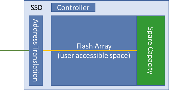
Figure 7, SSD spare capacity
Secure Erase algorithms must, therefore, be implemented in the SSD controller firmware.
NOTE: If there are bad flash cells/blocks, even the flash controller may not be able to overwrite that data. The controllers will typically make a best effort approach, but there is no guarantee that a bad cell can be overwritten. Similarly, if the flash controller fails, then none of the cells can be erased.
The available algorithms vary with the drive model chosen. Secure erase functionality may include certified algorithms, such as DOD 5220.22, NSA/CSS Manual 9-12, and RCC-TG IRIG 106-7 Chapter 10 as well as fast erasure techniques.
5.1 Erasing Contents vs Allocation Table
Note that the term “fast erase” is sometimes used to describe a process where only the allocation table of the FLASH controller is erased, and not the contents of the memory cells. In this case, the actual contents of the FLASH memory cells is left intact and could be read if the memory is removed from the device and accessed directly. The “secure erase” algorithm is completely different in that it physically clears each memory cell to an erased or other known state. The term “military erase” is often used as a reference to more advanced algorithms where each memory cell goes through a number of erase and overwrite cycles to ensure no user data is left behind in a readable state. Throughout the rest of this document, the terms fast erase, quick erase, and Zeroise refer to fast versions of secure erase – i.e. erase of the complete disk contents.
5.2 Secure erase algorithm options
Flash memory is designed to operate on a block basis, where all memory cells in a block are erased together, and individual cells may be written individually. It is not possible to erase a single cell. This restriction has some impact on the longevity of the device (refer to GEC-WP-1403, Galleon’s white paper on SSD technologies and flash memory wear out).
However, the block erase also helps with very fast complete disk erase. Running SSD erase based solely on flash memory block erase commands (issued by the SSD controller internally) is called ‘zeroise’, ‘fast erase’, or ‘quick erase’ (in accordance with notes in section 5.1 above).
Different SSDs implement different options for the other available algorithms. Note that many of the available options for erase algorithms were developed for magnetic media (HDDs), and it is unclear whether they actually offer much improvement on security of the data compared to simple flash erase (e.g. https://cseweb.ucsd.edu/~swanson/papers/Fast2011SecErase.pdf). In all cases, the SSD controller issues commands or writes data to the flash memory array, without any further interaction with the SSD host.
5.3 Initializing erase and erase duration
Galleon offers multiple methods for initializing the erase function, including:
- Discrete input
- API command
- Combination of discrete input and API command
Inside the Galleon product (XSR, G1, offload server or docking station), these commands are used to issue the correct command to the SSDs themselves.
Unfortunately, there is no standard defined for how to initiate the secure erase function. Consequently, the activation and algorithm depend on the vendor implementation. Some offer a way to trigger the secure erase through a discrete signal which is made available in a front panel connector on the SSD, or through one of the maintenance interface connections presents on the device. Some also support activation through a custom SATA command issued by the host OS.
The time it takes to perform a secure erase highly depends on the selected SSD manufacturer and type, as well as the algorithm required. The below table lists a number of algorithms and the related erase times for some representative drives.
*The times listed in the table below are given as estimates which apply to both hardware and software triggering of the erase sequences (where applicable). The actual time to complete varies with FW implementation, SSD vendor, FLASH type, software overheads, etc.
| Erase Methods | Erase Time | as a function | of SSD | Capacity |
|---|---|---|---|---|
| 128GB | 256GB | 512GB | 1TB | |
| D0h Clear | 7s | 14s | 17s | 34s |
| Quick/Fast Erase | 7s | 14s | 17s | 34s |
| Air Force AFSSI-5020 | 8m | 16m | 25m | 49m |
| DOD 5220.22-M | 8m | 16m | 25m | 50m |
| Navy NAVSO P-2539-26 | 8m | 16m | 25m | 50m |
| NSA 130-2 | 22m | 48m | 74m | 168m |
| ARMY AR380-19 | 22m | 48m | 74m | 168m |
| NSA 9-12 | 8m | 16m | 25m | 49m |
| IRIG 106-07 | 22m | 48m | 74m | 168m |
Table 3, Secure erase times (SSD level)
Note that these erase times are for individual SSDs, not for a multi-disk Data Module – erase times for the entire module may be up to a minute longer than the time per disk
5.3.1 Erase completion
For all algorithms and SSD based solutions offered by Galleon, once the erase command is issued to the SSD, the SSD controller will ignore all other commands until the erase process is completed. This applies even if power is removed. Once power is restored to the SSD, the controller will continue the erase process to completion. When this happens, the drives will not respond to any commands or accesses – they will appear to be defective or invisible.
5.4 Physical erase/destruction options
Some SSDs are available which implement a physical destruction methodology for data security. The mechanism employed is to apply very high voltage and high current to the flash memory cells. Theoretically, this will ensure that it is impossible to recover any data from the device.
Galleon Embedded Computing does not currently offer any of these devices within our recorders/NAS/servers, for 1 key reason:
- The manufacturers of these physical destruction SSDs have not been able to justify any reliable form of verification. Verification of the physical destruction method has (for the most part) been by confirming that the SSD is no longer accessible, or that the flash memory devices are no longer accessible. Neither of these techniques actually verifies that the flash storage cells have been destroyed (or that the same result would occur with all devices without exception). In the absence of clear evidence of verification of the destruction methods being used, Galleon cannot recommend these devices.
6.
Summary
Data security is an extremely complex subject – it should be considered throughout the phases of system design. It is much harder to add into existing systems.
There are many different mechanisms available which will secure Data at Rest for embedded systems. The best protection is typically found in a layered approach – using more than one mechanism to protect the data. Galleon Embedded Computing products are available with these mechanisms, either separately, or as multiple layers of protection.
Many encryption mechanisms add complexity to the system design and operation. However, the advantages of data being secure often outweigh the disadvantages of those added complexities. Data at Rest security can reduce the security requirements for the systems – for instance, it could save the need for armed guards to be stationed with equipment at all times. Similarly, employing the correct data security methods can also make easy disposal of old data modules possible which could otherwise be nearly impossible.
Each system has unique requirements which makes the selection of the optimal solution difficult. Galleon Embedded Computing has a wealth of experience advising and supporting system integrators with their selection of data security mechanisms.
7.
References
Common Criteria portal, https://www.commoncriteriaportal.org/
US government NSA’s CSfC pages, https://www.nsa.gov/resources/everyone/csfc/
FIPS 140-2 standard, https://csrc.nist.gov/publications/detail/fips/140/2/final
Web accessible paper: TKS1 – An anti-forensic, two level, and iterated key setup scheme, https://clemens.endorphin.org/TKS1-draft.pdf
Web article “Self Encrypting Drives”, (by Warwick Ashford, ComputerWeekly.com), https://www.computerweekly.com/feature/Self-encrypting-drives-SED-the-best-kept-secret-in-hard-drive-encryption-security
Web article “ATA Secure Erase” (Linux ATA Wiki), https://ata.wiki.kernel.org/index.php/ATA_Secure_Erase
Web accessible paper: Reliably Erasing Data From Flash-Based Solid State Drives, https://cseweb.ucsd.edu/~swanson/papers/Fast2011SecErase.pdf
Opal Specification, from the Trusted Computing Group, https://trustedcomputinggroup.org/wp-content/uploads/TCG_Storage-Opal_SSC_v2.01_rev1.00.pdf