Abstract
This document provides a review of Network Attached Storage (NAS) applications and discusses the features which should be considered when specifying a NAS requirement. NAS Devices are then compared with Data Recorders and Direct Attached Storage (DAS). The final part of the document reviews Galleon Embedded Computing’s NAS products, providing ideal NAS platforms for rugged environments where space is at a premium.
1.
Introduction
1.1 Background
Network Attached Storage (NAS) is a term used for any type of storage device attached to any computer network. Most commonly, it refers to a file-level computer storage device on an Ethernet Network (GbE, 10GbE, etc.).
This tech note discusses some of the applications for NAS in rugged systems, and the selection criteria which are valuable for ensuring the best solution.
1.2 Network Attached Storage vs Data Recorder
Network Attached Storage (NAS) devices allow other computers in the network to access files, creating files with their own defined formats, and editing and moving files as desired.
Data Recorders serve a very similar function in many cases, especially when recording Ethernet traffic. However, the data recorder is passive in that the data source doesn’t need to know that the data is being recorded, and the control computer only has to send simple commands to the recorder. Many data recorders also implement NAS functionality, allowing users to read from the recorded data files.
The features of each are briefly shown below.
Table 1, NAS compared to Data Recorder
| Storage System | NAS (Network Attached Storage) | Data Recorder |
|---|---|---|
| Features | The data source/sender actively performs read/write accesses to the storage device. All data sent to the NAS is stored – the data won’t be sent until the NAS is ready/enabled. File formats are defined by separate computers writing to the NAS. NAS functionality allows all computers on the network to access the file system (read and write, depending on user access controls). | Data recording is passive - the data source (typically a sensor or similar) doesn’t need to have any knowledge that the recorder exists. A control computer sends simple commands to control the recorder. The data source is often free running, and the recorder will grab data (as commanded) when required. Typically, not all data is recorded. File formats are defined by the data recorder software. Data Recorders can do playback of data, but access to the recorded data files is only available if NAS functionality is added. |
1.3 NAS vs DAS
Network Attached Storage (NAS) is designed to be completely independent of the storage technologies, connectivity, and sizes.
Direct Attached Storage (DAS), on the other hand, uses the underlying storage devices (drives) connections to connect into the computer systems to be used.
The features of each are briefly shown below.
Table 2, NAS compared to DAS
| Storage System | NAS (Network Attached Storage) | Data Recorder |
|---|---|---|
| Features | Portable (can be used by any computer system with Ethernet connections) Simplified obsolescence management (Ethernet connections) Independent of Operating Systems Low cost and low risk (Industry standard connectivity/cabling/etc) Long cables/connections via switches Mixed technologies available (GbE/10GbE) One NAS may be shared by many computer systems User/role based access levels to different sections of the data | Fixed connectivity (cabling must be changed if drive technology changes) Expensive / custom cabling / board connectivity – typically relatively short distances Computer system controls disk bandwidth directly Separate DAS required per computer system |
2.
Example NAS applications
Some examples for Network Attached Storage (NAS) applications are described below.
Note that NAS devices typically get used for a mixture of these applications – NAS devices are independent of the type of data being stored. NAS capabilities/features all relate to general data storage and data access, often simultaneously.
2.1 Mission data recording
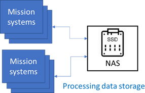
A typical application of this type is with processing systems which need to dump some data to a NAS during operation. The data can be stored for post-mission analysis, but can also be accessed by users and decision makers while the operation is still on-going.
One of the advantages of NAS compared to other methods of transferring data between deployed platforms and base stations is the ability for all of the networked computer systems to access the same centralized data storage system.

2.2 Mission data planning
The NAS is loaded with data (e.g. moving map data, and other planning parameters) before the mission, and the processing systems can access that data during the mission.
Again, the NAS system provides the ability for all networked computers to access the data inside the NAS storage, so all data can be transferred from base station on a single removable data module.

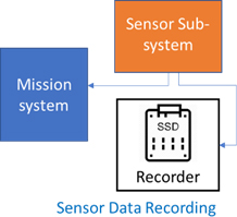
2.3 Sensor data recording
Sensor data can be sent to the NAS during a mission for post-mission analysis. The sensor data typically goes directly to the mission system still, but for post mission analysis, the data is stored on a NAS.
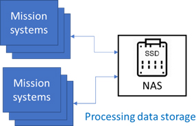
2.4 General non-volatile data storage
Mission systems may require some non-volatile storage for part of the mission parameters. The data is written to the NAS as required, and read back when needed, perhaps much later in the mission.
3.
NAS specification features
For any application needing a NAS, there are certain criteria that are important to understand, as well as some of the pitfalls hidden behind some of the datasheet figures.
- Storage size
- Storage technology (affecting reliability, longevity, )
- Portability/upgradeability
- Connectivity
- Access bandwidth (read and write, and simultaneous)
- Data Security and user access control
- Pre and Post-mission offload/access to data
- Reliability in a rugged environment
- Size, weight, power and cost Each of these is discussed
3.1 Storage size
This is relatively obvious – select the storage size that will provide you with enough space for the worst case activities required for any particular application/system.
However, storage size specifications often vary between products/vendors, so there is a common pitfall that needs to be understood.
SSDs are specified by the total size of the flash memory array, but some of that space is actually used as ‘spare capacity’ to account for flash memory wear out. Because of this, the user addressable space is normally around 10% less than the headline figure.
So, when specifying NAS size, it is sensible to allocate an extra 10% for this, and other considerations (e.g. if the application/algorithm changes slightly with later upgrades, more storage might be required).
Similarly, operating the drives inside the NAS as a RAID array will use up a small amount of the drive. For RAID0, this is a very small overhead (for identifiers related to the RAID array), but for other RAID formats, significant amounts of storage are lost for duplication or other redundancy and data recovery mechanisms.
3.2 Storage technologies
Some of the current options for NAS storage are listed in the table below, with comments on advantages and disadvantages:
Table 3, Storage Technologies
| Storage | Comments |
|---|---|
| Hard Disk Drive (HDD) | Rotating magnetic media (HDDs) will often provide the most cost effective option for very large storage requirements. Due to HDDs using moving parts in their design, this often provides a low reliability especially when used in Rugged applications where shock, vibration and altitude may be a concern. Failure modes for HDDs are typically random (classic MTBF type failures) HDD disk bandwidths will vary in an unpredictable way – this is dependent on location on the disk (due to mechanical head movement), age of the disk, and other factors. IOPS (Input / Output Operations per Second) are very limited for HDDs, because of the mechanical head movement required. Therefore, HDDs performance is particularly poor for random accesses such as database lookups, mapping information, etc. |
| Solid State Drive (SSD) | SSD technology is based on flash memory for non-volatile storage There are multiple different types of SSD (SLC, MLC, etc.) – these are discussed in Galleon’s white paper “SSDs in mil and aerospace applications” ref: GEC-WP-1403 SSD technology can be extremely reliable (very high MTBF), but it is affected by “Flash wear out” Flash wear out is predictable and therefore preventative maintenance can be used by making use of the SMART (Self-Monitoring, Analysis and Reporting Technology) information available from the SSD. This is discussed further in the white paper mentioned above (GEC-WP-1403) |
| Fixed flash memory | This is similar to a NAS built out of SSDs, but has a separate connection into the flash memory instead of being through an SSD controller. This is typically used for custom applications, and isn’t discussed in more detail here. Such a device may have the same protection mechanisms against flash wear out as most SSDs, but that will depend on the design parameters for each device. |
3.3 Connectivity
NAS devices are specified by the Ethernet connections which they support. In most cases, that will be all of one type (e.g. all GbE 1000Base-T, or all 10GbE), but it can also be a mixture. One key advantage to NAS devices is that they can provide multiple different Ethernet connections into the same storage media.
Note that NAS devices use industry-standard (Ethernet) connectivity. As such, the cabling requirements are simple and typically easy to implement with high confidence.
For a particular system, there may be a requirement to have a mixture of Ethernet connections
– e.g. perhaps GbE ports are used for streaming sensor data to the NAS, but a 10GbE port is desired for fast access by the backend processor which is using that data. Similarly, 10GbE can be used for fast copying of data to/from the NAS at the start and end of a mission (may also be enhanced if removable storage is used).
So, it is important to know how many physical links, and of what type, the NAS will need to provide.
3.3.1 Network performance
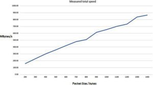
NAS read/write bandwidth is often limited by network performance. Using large packet sizes, jumbo frames, etc. will all improve network performance which would also improve NAS bandwidths. Note that controlling packet sizes is easier for a data recorder application (with a data streaming device sending the data) than it is with a NAS. But NAS applications can impact on performance in how they access the NAS – lots of separate small file accesses will see poor performance. The graph below shows a typical analysis of bandwidth against packet sizes on 10GbEthernet.
3.4 Portability/Upgradeability
NAS devices which use GbE and 10GbE connectivity are relatively easy to move between different platforms, and to be upgraded and replaced when needed (for obsolescence or other reasons). The rest of the computer system is largely unaffected, as long as the bandwidth and connectivity is the same. Even an upgrade to a NAS system from GbE to 10GbE doesn’t need to affect existing computer systems/network infrastructure/switches. It just requires a NAS which supports both types of Ethernet port:
3.5 Access bandwidth
Some of the pitfalls here relate to high level feature lists. For example, a NAS which has 4x 10GbE ports cannot necessarily support all ports operating at full bandwidth at once. NAS devices often use RAID0 arrays of storage devices at very high bandwidth, but still the available bandwidth may be lower than the maximum total bandwidth available on the Ethernet and 10GbE connections into the NAS.
Note that achievable bandwidths for NAS devices vary with the activity achievable – e.g. NAS bandwidth for very small Ethernet packet sizes is much lower than with large packets and Jumbo Frames. This is partly a factor associated with the Ethernet links, but it is also affected by the NAS device’s ability to deal with the packetization of the data. For this reason, there are often no ‘headline’ figures for bandwidth published for NAS devices. Instead various figures are available with some stated (or not stated) conditions of measurement. If only one set of bandwidth figures is published, it is possibly only relevant for the very best conditions, and wouldn’t be realistic for a real world application.
Similarly, Bandwidth for a NAS when all activity is writing can be very different from when all activity is reading, or when there is a mixture of reads and writes.
3.6 Data security and Access control
Data security relates to protection of the data from being accessed/read by people who shouldn’t have access. It covers data-at-rest protection mechanisms, as well as protection during active use.
NAS devices provide data security using a variety of techniques including:
- Encryption – either using self-encrypted disks or with separate encryption in the data path to the disks
- Secure erase – the ability to erase the data on the disks in a way which makes it impossible to recover the data
- Access controls – different users can be enabled to access different parts of the NAS disks file system
3.7 Pre- and Post-Mission access to data
Commercial NAS devices don’t have this as a consideration because they are designed to only ever be accesses over the Ethernet connections.
Rugged NAS devices vary in how you can transfer data to/from the rugged platform before and after the mission.
Table 4, Data transfer methods pre- and post-mission
| Data Access | Comments |
|---|---|
| Removable storage | A physically small removable data module provides the fastest/simplest method for transferring data to/from a NAS and the base station. Some sort of offload computer (allowing the data on the removable data module to be copied onto base station computer storage) is required, and can be provided with extremely high bandwidth capabilities, so data from a mission lasting several hours can often be transferred in a fraction of that time. If very fast turnaround for the next mission is required, two removable data modules can be used in rotation. |
| Fast offload/data transfer ports | As an example, a NAS with many GbE ports being used on the mission could have a 10GbE port for faster transfer of the data to some other computer system before and after the mission. |
| Using standard NAS ports | This is the simplest solution – just use the ports which are used during the mission to transfer data to/from the NAS before or after the mission. In many cases, this can be a problem with several hours being required in some cases just to transfer the data. During that time, the NAS must be powered, and the platform can’t go for another mission until the transfer is complete. |
3.8 Reliability in a rugged environment
Having a NAS which fails as soon as the temperature goes too high or low, and which interferes with other equipment isn’t useful.
Different equipment manufacturers have differing attitudes to the necessary steps for validation of their products against the specifications selected (MIL-STD-810, MIL-STD-461, etc.). For instance, claims of ‘compliance by design’ for vibration or shock testing are of debateable value.
The specifications themselves have many different levels defined, so it is sensible to confirm that the equipment being considered has been tested at similar levels to those which will be required in the deployed system.
3.9 Size, Weight, Power, and Cost
These are the same considerations as for all equipment – NAS devices come in many shapes and sizes, and vary hugely on cost. Finding the smallest one which meets the other requirements criteria is often a challenge.
4.
Galleon NAS devices
This chapter details the features of the Galleon G1 rugged microNAS.
Galleon also have alternative NAS devices available with more processing power, larger storage, higher bandwidths, and alternative IO (e.g. multiple 10GbE ports). Some of these are described in the next chapter. The G1 is the best fit where small size is required and wherever the G1 IO is sufficient for the application.
4.1 G1 microNAS
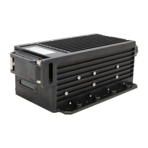
G1 MicroNAS
Figure 1, G1 microNAS
The G1 is part of Galleon Embedded Computing’s product range, and supports operation as a NAS, Server/computer, or recorder, as required for each application.
The G1 microNAS is described HERE
4.1.1 G1 feature list
The G1 microNAS provides huge storage capacity in a tiny package.
- Four GbE (1000Base-T) ports on rugged circular connector
- One 10GbE (10GBase-T) port on rugged circular connector (optional)
- Up to 40TB removable data module for storage – sizes from 1TB to 40TB
- Up to 600MB/s read/write bandwidth
- Encryption, secure erase and role-based access control options
- 25W (typical quad port NAS activities)
- 28V nominal power (12-48V range, tested to MIL-STD-704)
- Weight <1.2kg including removable storage
- 83 x 63 x 185mm/3.2 x 5 x 7.2″
4.1.1 G1 NAS bandwidths
Tests performed on the G1 design are outlines below – these give guidance on the sustained bandwidths which can be expected to be achieved with the G1. Note that the realisable bandwidth in any particular system is dependent on the ‘other end’ of the Ethernet links.
The table below shows the bandwidths achieved for NAS activity on the G1 microNAS:
| Configuration | Write (MB/s) | Read (MB/s) | Power (W) 1 |
|---|---|---|---|
| 1-port GbE NAS | 110 | 111 | 20.4 |
| 2-port GbE NAS | 225 | 223 | 21.4 |
| 4-port GbE NAS | 450 | 418 | 24.0 |
| 1-port 10GbE NAS | 220² | 658² |
Table 5, G1 microNAS bandwidths
1.Note that power figures quoted here are representative, but may vary compared to deployed systems depending on power voltage, temperature, SSDs being used inside the RDM (Removable Data Module), etc.
2.Bandwidth figures for 10GbE NAS are based on measurements made with simultaneous read and write using NFS (4 files being written, 4 files being read from). Higher bandwidth writing has also been achieved when isolated.
For comparison, consider that the peak bandwidth possible over 4 GbE links is 500MB/s (4x 1Gb/s, or 4x 125MB/s). The sustained bandwidths achieved show that the bottleneck is the Ethernet connections and overhead in packetization; the disk bandwidth is not the limiting factor.
Additional testing of a customized G1 with a single 10GbE port has shown bandwidths in excess of 600MB/s, with disk (RAID0 array) read bandwidth over 900MB/s. This is from a development project, with productization currently underway.
4.1.3 Low power single port NAS
The G1 has also been tested to explore the possibilities for very low power NAS operation. For this testing, the processor inside the G1 had 6 of the 8 cores disabled.
| Configuration | Write (MB/s) | Read (MB/s) | Power (W) 1 |
|---|---|---|---|
| 1-port GbE NAS, Idle | n.a | n.a | 9.2 |
| 1-port GbE NAS, standard 4KB packets | 80 | 95 | 12 |
| 1-port GbE NAS, 4KB with Jumbo Frames | 97 | 108 | 12.1 |
| 1-port GbE NAS, 1MB packets | 110 | 108 | 11.6 |
| 1-port GbE NAS, 1MB with Jumbo frames | 115 | 113 | 11.6 |
Table 6, G1 microNAS low power bandwidths
4.1.4 G1 data offload/transfer
Offload of the data may be performed using the 4 Ethernet ports or the optional 10GbE port, but it is often faster and simpler to remove the RDM (Removable Data Module) and use the docking station which Galleon also provides to transfer the data to/from another computer system over USB3 ports.
The USB docking station shown below may be used to provide easy and high bandwidth access to the storage in the RDM for copying data onto or off the RDM pre- and post-mission.
The docking station is designed for benign environments. More details (including documentation) are available on the Galleon website HERE.
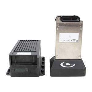
Figure 2, G1 USB docking station
If a rugged offload solution is required, then another G1 NAS can be used – accessing the data overall 4 Ethernet channels allows over 400MB/s offload speeds (as shown in Table 5 above). Access over the optional 10GbE channel provides much higher bandwidth.
4.2 XSR NAS products
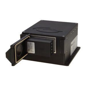
Figure 3, XSR NAS and Removable Data Module (RDM)
The XSR small form factor NAS is shown above, and more information/documentation is available at HERE
4.2.1 XSR NAS feature list
The XSR NAS provides additional bandwidth, disk capacity and IO options when compared to the G1 microNAS described above.
- Up to 13 GbE (1000Base-T) ports on rugged circular connector
- Up to 8 10GbE ports (optical, expanded beam rugged connector)
- Up to 2 10GbE ports (Electrical) ports on rugged circular connectors
- Options for a mixture of GbE and 10GbE connections
- Up to 80TB removable data module for storage – sizes from 1TB to 80TB
- Over 1GB/s read/write bandwidth
- Encryption, secure erase and role-based access control options
- 60-70W (typical NAS activities)
- 28V nominal power (16-40V range, tested to MIL-STD-704)
- <5kg
- 157 x 201 x 103mm (6.2 x 9 x 4.1″) (or 194 x 341 x 89mm (7.6 x 13.4 x 3.5″) depending on IO requirements)
The quad server is not just a NAS, but it is often used for NAS functionality as well as processing. It has the same features as the XSR NAS, but it also has 3 extra processor subsystems included (and it is larger than the small form factor XSR).
The quad server is described in separate documentation accessible via the Galleon website HERE
4.2.3 XSR NAS bandwidths
NAS bandwidths for the XSR vary depending on the IO technology being used, as well as the Removable Data Module (RDM) selected.
For most NAS applications, sustained bandwidths of 800MB/s are achievable, with some configurations of the XSR exceeding 1GB/s.
More details can be provided, after the specific IO configuration is known.
4.2.4 XSR data offload/transfer
Offload of the data may be performed using the Ethernet (GbE or 10GbE) ports, but it is often faster and simpler to remove the RDM and use the docking station or offload servers which Galleon also provides to transfer the data to/from another computer system.
A 19” rackmount offload server is available which provides a powerful desktop processor system with a slot for the RDM, and sufficient disk space available to store data from several missions. More details (including documentation) are available on the Galleon website HERE
A portable version of the above offload server is also available, called the portable Planning and Debriefing System (PDS), shown below. The specification and options are very similar to the 19” rackmount offload server.
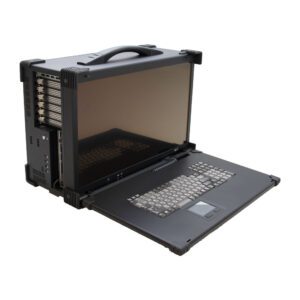
Figure 4, portable Planning and Debriefing System, PDS
Also, a USB docking station is available, similar to the G1 docking station described above in section 4.1.4. More details (including documentation) are available on the Galleon website HERE
4.3 Storage Technology
The Removable Data Modules (RDMs) for both the G1 and the XSR use advanced SSDs, so protection against flash wear out is built into the NAS. Tools for monitoring the SMART information on the SSDs are provided on the NAS.
4.4 Qualification testing
The G1 and XSR are tested for operation in rugged environments, against MIL-STD-810G and MIL-STD-461F standards, and some testing against DO-160 standards. Details of the test parameters and results are available under NDA.
5.
Questions or Comments
This tech note will be updated when necessary.
Any questions or comments to the contents are welcome and appreciated. Please contact Hugh Tarver, at htarver@galleonec.com or send your feedback to info@galleonec.com


