

XSR Write Protection
Abstract: XSR Write Protection: Safeguarding Mission-Critical Data The XSR Write Protection, offered by Galleon Embedded Computing, serves as a critical security feature within their rugged and secure storage solutions and data recorder systems. This feature is designed to prevent unauthorized modification or deletion of data stored on XSR products, ensuring the integrity and security of mission-critical information in challenging operational environments. Part of Galleon’s extensive product line, which includes servers, NAS devices, mission computers, and more, the XSR Write Protection reinforces the company’s commitment to providing reliable and secure solutions for military air, land, and sea platforms. As part of Spectra Aerospace & Defense, Galleon Embedded Computing continues to demonstrate its dedication to delivering robust and battle-tested technology tailored for aerospace and defense applications.
1.
Write Protection
1.1 Introduction
Galleon XSRs have several non-volatile (NV) devices that are not accessible from standard operating software. However, periodic firmware upgrades on some NV devices require to write access for special equipment or software. To ensure these devices are not inadvertently written to, hardware write protection is available.
The internal system drive SSD containing the operating system may also be write-protected to satisfy security requirements.
1.2 Write-protected Devices
The following are examples of internal NV devices that can be write-protected through hardware:
- Ethernet configuration PROMs
- PCI-Express configuration PROMs
- XMC devices
- MCU FLASH
- Configuration EEPROM
- System Drive (if drive is equipped with write protection)
1.3 Non Write-protected Devices
The following are examples of internal NV devices that are not write protected through hardware. In these cases, utilities exist to erase or program the NV devices to a known state.
- USB configuration PROMs
- SATA controller FLASH
- XMC devices
- FPGA FLASH
- BIOS
- Removable Data Module (RDM)
1.4 J1 Control and Management
The Galleon XSR has two digital I/O connectors of type Glenair Mighty Mouse series 801, size 13-37 in the rear panel. J1 provides the control and management interface. The connector provides the following control interface signals:
- 1x VGA Output
- 1x 1000 base-T Ethernet Interface
- 2x USB 2.0 Interface
- Miscellaneous
Figure 1 J1 Control
| XSR Connector type: | Glenair p/n: 801-009-07ZNU13-37SA |
|---|---|
| Mating Cable connector (example): | Glenair p/n: 801-007-16ZNU13-37PA |
| Mating Galleon Cable: | XSR-CBL-BRK37A-006 |
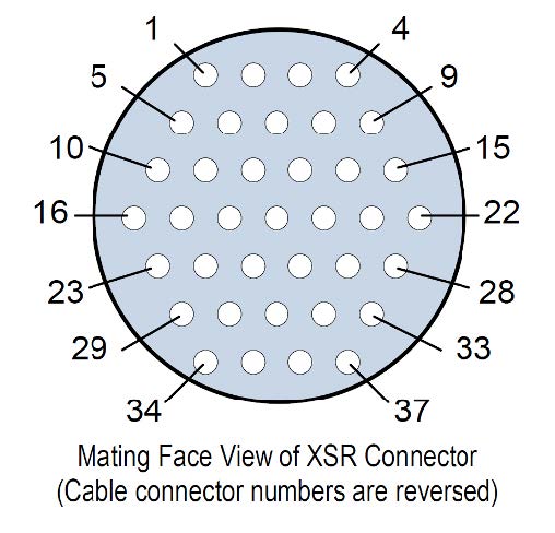
Figure 2 J1 Control
1.5 J1 Write Protect Signal
The write protect signal is located on pin 12 of J1. The signal is marked as reserved, NVWE# or NVWP# in the delivered Interface Configuration Description (ICD) depending on the system configuration.
The signal is pulled up through an internal resister in the XSR such that when left disconnected, it is in an inactive state. When pulled (tied) to ground through pin 12 of J1, the signal is in an active state. The active-low state is factory configured as write enable (NVWE#) or write protect (NVWP#) depending on customer requirement. The default configuration is active-low write enable (NVWE#). In the default configuration, the XSR NV devices are write protected when pin 12 of J1 is left disconnected.
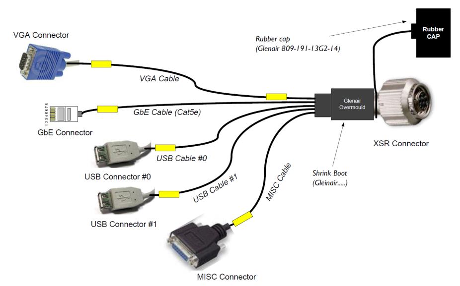
Figure 3 XSR-CBL-BRK37A-006
Galleon provides a special lab cable that provides access to the write-protect signal on J1. The write protect signal is connected to pin 2 on the MISC DB15 connector on Galleon cable XSR- CBL-BRK37A-006.
Using the lab cable, the NVWE# or NVWP# pin can be tied (pulled) to the ground using a simple jumper between pins 2 and 9 (GND) on the MISC connector.
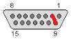
Figure 4 MISC DB15 Connector
1.5.1 write-protected System Drive Write Protect Signal
System drive SSDs are available with or without write protection built in. When using an SSD that is not equipped for write protection, the J1 write protect signal has no effect on the system drive. In this manner, the J1 write protect signal can be configured for NVWE# to protect other NV devices yet still enable writing of the SSD. This is the default configuration.
When using an SSD equipped with write protection, the NVWE# signal must be pulled low in order enable writing of the SSD. When NVWE# is pulled low, all other NV devices are also enabled for writing. Alternatively, when the write protect signal is configured for NVWP#, it is normally write enabled and must be pulled low to enable write protection on the SSD and other NV devices.
1.6 Read-Only Operating System Configuration
When the system drive SSD is configured as write protected, the operating system must be told to mount in read-only mode. This is initially done during the partitioning of the the SSD during Linux Installation.
Depending on the O/S, a screen similar to the one shown below will allow for the disk to be partition in read-only mode. Both “noatime” and “ro” should be selected during initial portioning.
Once installation is complete, the operating system is placed in read-only mode, but also creates a RAM disk where all temporary files are stored (i.e. /tmp, /var, etc.) The contents of the RAM disk are lost when power to the system is removed.
When the system comes back up, the root and any other system partitions will be mounted
read-only. All the files and directories listed in /etc/rwtab will be mounted read-write on the tmpfs filesystem in RAM. Additional files and directories can be added to rwtab to make them writable after reboot.
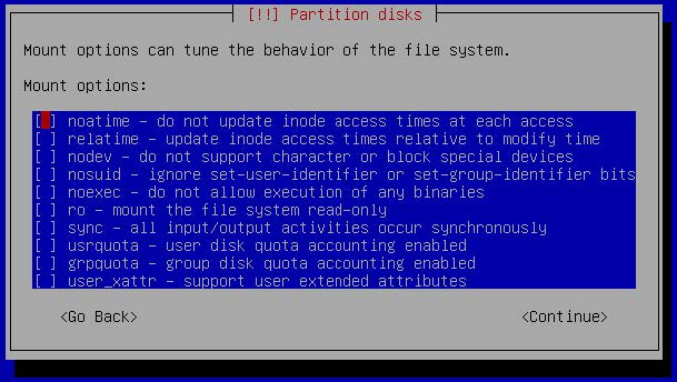
Figure 5 SSD Partitioning
1.6.1 Placing read-only system in write mode
To change any system parameters (i.e. IP addresses, user credentials), to add or modify software, etc, a utility is supplied to enable temporary write access to the system drive. The utility will change the mode of the file system to read/write.
Note that the write protection applies to the system SSD only. User data is normally stored on the removable data cartridges which are not write protected. The default mount point for user data is /data.
The following steps are required to perform changes to the read only file system:
1. Make sure the hardware signal is configured to disable write protection (#NVWE pulled low on normally protected systems or #NVWP floating on normally enabled systems).
2. Boot the operating system
3. Run the following command to enable file system r/w operation:
# sys-suspend-read-only
This script is used to disable the read-only configuration of the system drive temporarily, allowing the operator to perform maintenance that requires write access to the system drive.
The script starts by checking the state of hardware write-protection on the system drive. If hardware write-protection is activated, the script will just display an error message and terminate, leaving the system drive mounted as read-only.
If write-protection is deactivated, the script will remount the system drive as writable, and unmount all files and directories that are mirrored on RAM disk (tmpfs). The system drive will remain in this writable state until the system is rebooted.
4. Perform the changes required to the system
5. Reboot to place system drive back into read-only
1.6.2 System Drive Dependencies
Galleon currently provides hardware write-protected system drives from two different manufacturers. Attempting to write to a write-protected drive will result in no data being written to the drive in either case. However, the response from the drive will differ between the two manufacturers.
When considering the response of the hardware write-protect, it is important to understand that the operating system will first determine validity of the write prior to writing data to the drive. An error will be returned from the operating system if it determines the operation is invalid for a read-only drive and the write will not be performed. In this manner, the “readonly-root” configuration takes precedence over the hardware write-protect.
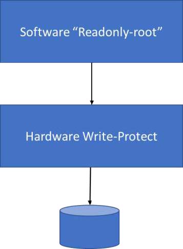
When in “readonly-root” mode, the operating system will not attempt to write to any part of the root partition “/” of the drive.
As an example, if one were to attempt to create a directory in the root file system (e.g. #mkdir/newdir), the operating system would respond with an error that the directory cannot be created: “unable to create directory <…>, read-only file system”
This is not true for files and directories placed in the temporary filesystem located in RAM disk. They may be freely written because they are placed in RAM. Temporary files (/tmp directory) and log files (/var directory) fall into this category. Similarly, other files and directories may be placed in RAM by listing them in /etc/rwtab. These will be mounted read-write on the tmpfs filesystem upon boot up.
See https://access.redhat.com/solutions/40906 for additional information.
If, on the other hand, an operation is performed outside of the root file system, yet still on a partition of the write-protected drive, this is where the differences between drives will appear.
1.6.2.1 TCS Drive
If another partition of the write-protected drive is mounted under the mount point “/mnt”, the operating system does not know whether this is a local drive or remote mount of another drive. A write to “/mnt” will proceed from the operating system to the drive, but the drive will not allow it to happen because it is hardware write-protected. The data will not be written to the drive. On the TCS drives, a series of error messages will appear.
For example, when executing:
where ‘/mnt/’ is the mount point of a file system on a write-protected TCS Drive, you get 7 repetitions of the following error messages:
ata4.00: exception Emask 0x0 SAct 0x0 SErr 0x0 action 0x0
ata4.00: irq_stat 0x40000001
ata4.00: failed command: WRITE DMA
ata4.00: cmd ca/00:08:3f:20:04/00:00:00:00:00/e0 tag 0 dma 4096 out
res 51/40:08:3f:20:04/00:00:00:00:00/e0 Emask 0x9 (media error)
ata4.00: status: { DRDY ERR }
ata4.00: error: { UNC }
ata4.00: configured for UDMA/133
ata4: EH complete
followed by:
sd 3:0:0:0: [sdc] Unhandled sense code
sd 3:0:0:0: [sdc] Result: hostbyte=DID_OK driverbyte=DRIVER_SENSE
sd 3:0:0:0: [sdc] Sense Key : Medium Error [current] [descriptor]
Descriptor sense data with sense descriptors (in hex):
72 03 11 04 00 00 00 0c 00 0a 80 00 00 00 00 00
00 04 20 3f
sd 3:0:0:0: [sdc] Add. Sense: Unrecovered read error – auto reallocate failed
sd 3:0:0:0: [sdc] CDB: Write(10): 2a 00 00 04 20 3f 00 00 08 00
Buffer I/O error on device sdc1, logical block 33792
lost page write due to I/O error on sdc1
1.6.2.2 Virtium StorFly Drives
In the same scenario described in Section 1.6.2.1, the Virtium drive will also not allow the data to be written to the drive, but no errors will appear. The drive will simply discard the data and not report any errors.
This is actually the preferred method, as the controller detects it is an invalid operation earlier in the process and does not present error messages as artifacts.
1.7 Conclusion
By properly configuring the write protect pin on the J1 connector, most NV devices on the XSR can be write protected. Special consideration to a write protected system disk should be given during installation and when performing updates for proper read-only system operation.
DOWNLOAD PDF